


17
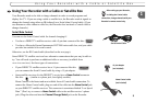
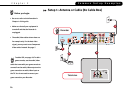
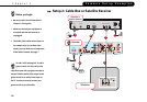
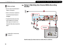
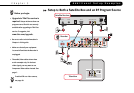
Setup 2: Cable Box or Satellite Receiver
2
1. Check that the cable from the wall is connected to the cable or satellite box.
2. Connect the Composite A/V cable from the Audio/Video Output connectors on the
cable or satellite box to the Audio/Video Input 1 connectors on the Recorder.
3. Connect the Composite A/V cable from the Audio/Video Output 1 connectors on the
Recorder to the Audio/Video Input connectors on the TV.
4. Connect a phone line (see page 8 for help). After you complete Guided Setup (see step
10 below), you’ll be able to connect your Recorder to a home network and use a shared
broadband Internet connection instead of a phone line to connect to the TiVo service.
See Chapter 8, “Connecting to a Home Network,” in the User’s Guide.
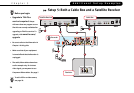
5. Select a channel changing Control cable (see page 9 for help). You can use the Serial
Control cable if you have a DIRECTV satellite receiver with a 9-pin data connector, or
a Motorola/General Instruments DCT2000 series cable box. If you choose the Serial
Control cable, continue with step 6. For any other satellite receiver or cable box,
choose the IR Control cable and skip to step 7.
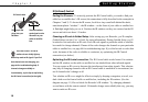
6. Connect the Serial Control cable. Plug one end of the Serial Control cable into the
Data connector on the satellite receiver or cable box. Plug the other end into the
Channel Change/Serial connector (the lower mini-jack) on the Recorder. Then skip
to step 10.
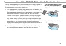
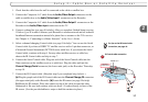
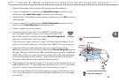
7. Connect the IR Control cable. (Skip this step if you completed step 6 above.)
(a) Plug the purple end of the IR Control cable into the Channel Change/IR connector
(the upper mini-jack) on the Recorder. (b) Locate the IR sensor (see page 9 for help).
(c) Mount the IR emitters. Place one emitter on top of the cable box and the other
underneath it. Be sure both emitters stick out about 1.5 inches directly in front of the
IR sensor. (Use the provided adhesive strips to hold the emitters in place.)
extends 1½ "
Cable Box or
Satellite Receiver
a
Recorder
®
b
c
IR Control cable connection
7
For tips on the IR Control cable
connection, see page 10.
®