


4
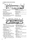
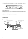
5. NOMENCLATURE AND FUNCTIONS
[Front]
1. Power switch
Turns the power on when pressed.
Turns it off when pressed again.
2. Power indicator
Lights when power is on.
3. Wireless microphone volume control
Adjusts the wireless microphone volume.
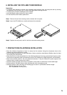
4. Front panel mounting screw
When installing the optional WTU-4800 Diversity
Wireless Tuner Module, remove two screws to
detach the front panel. Refer to p. 5.
5. Front panel
Detach this panel when installing or removing the
WTU-4800 tuner module. Refer to p. 5.
6. Reception indicators
Either lights to indicate which antenna A or B
receives a radio signal.
7. Peak indicator
Lights when a receiving wireless microphone
signal is distorted.
8. Channel selector switch
Sets the receiving channel.
[Rear]
010 010
ANT A
ANT B
PEAK
VOLUME
CHANNEL
TUNER
1
ANT A
ANT B
PEAK
VOLUME
CHANNEL
TUNER
2
ON
OFF
POWER
DIVERSITY WIRELESS TUNER WT-4820
1
2
3
4
5
6
7
8
OUT ININ
DC IN OUTPUT MIX IN
MIX/12
ANT AANT B
-20dBV/600Ω(+6dBV Max)
12-18V
250mA(max)
-20dBV/10kΩ
(BALANCED)
SELECTOR
MIX 1
(UNBALANCED)
HOT
COLD
12
3
10
11 12 1614 15
9
13
17
18
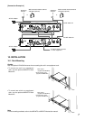
9. Antenna B input connector
BNC jack, 75 Ω.
Connects to the supplied antenna or the optional
YW-4500 Antenna. When using the supplied
antenna, tilt it about 45° out from upright position.
10. Power input connector
Connects to an AC-DC adapter.
11. Cable hanger
Hook the power cable onto this part.
12. Solo output 2 terminal
–20 dB (+6 dB max.), 600 Ω, unbalanced.
Outputs the tuner module 2 signal.
13. Mix/solo output 1 terminal
–20 dB (+6 dB max.), 600 Ω, unbalanced.
Outputs either the mixed signal of the tuner
modules 1 and 2, and the Mix input (16) source
or the tuner module 1 solo signal.
14. Mix/solo output 1 selector switch
Selects the type of signal to be outputted from
the Mix/solo output 1 terminals (13) and (15).
MIX: Outputs the mixed signal of the tuner
modules 1 and 2, and the Mix input (16)
source.
1: Outputs the tuner module 1 solo signal.
15. Mix/solo output 1 terminal
–20 dB (+6 dB max.), 600 Ω, balanced.
Outputs either the mixed signal of the tuner
modules 1 and 2, and the Mix input (16) source
or the tuner module 1 solo signal.
16. Mix input terminal
–20 dB, 10 kΩ, unbalanced.
Connects to an additional wireless tuner for
expansion.
Refer to p. 7.
17. Antenna A output connector
BNC jack, 75 Ω.
Used to add a wireless tuner (totaling two tuners)
without need for extra antenna mixers or
distributors.
18. Antenna A input connector
BNC jack, 75 Ω.
Connects to the supplied antenna or optional
YW-4500 Antenna.
When using the supplied antenna, tilt it about 45°
out from upright position.