


40
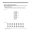
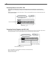
Connecting a PTZ Camera
Setting up a PTZ Camera is simple. The DVR comes preassembled with an internal PTZ adapter. The cabling may be run up to 4,000
ft using 22 Gauge Twisted Pair.
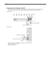
It is important to understand how the PTZ connects to the DVR. The DVR outputs an RS-232 signal and converts in to an RS-422/485
signal which is then sent to the PTZ camera.
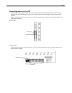
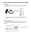
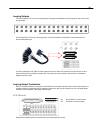
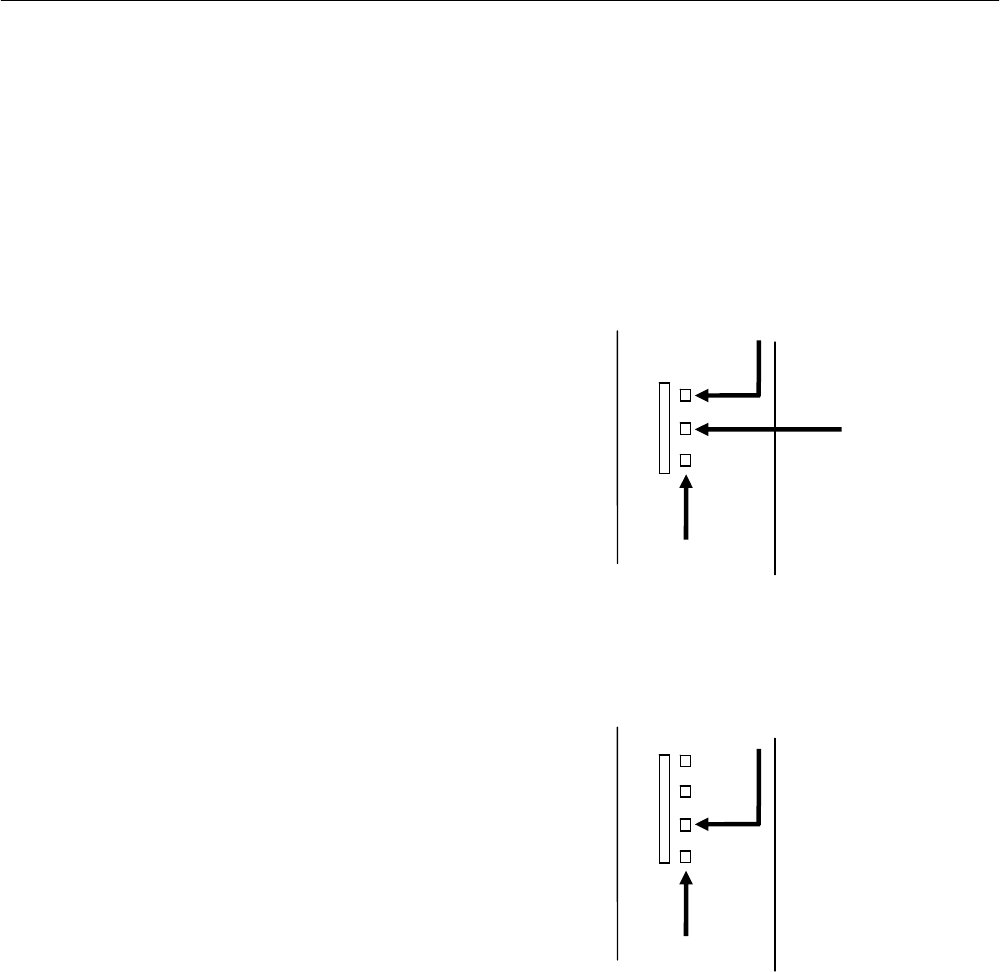
Attaching the 3-Pin Adapter
1. Locate the PTZ adapter cable.
2. Connect the two wires of the PTZ adapter to the PTZ camera.
The red wire on the adapter should connect to the RX+ on the
PTZ and the brown wire should connect to the RX-.
3. Connect the other end of the adapter to the DVR as shown.
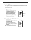
4. Assign the PTZ camera an ID number in PTZ Setup that
coincides with the number assigned to the camera. This is
normally done utilizing a dip-switch configuration method on the
addressable dome.
Tip Toshiba recommends that the ID of the camera coincide to
the input number on the DVR. This will make future
troubleshooting and configuration less complex.
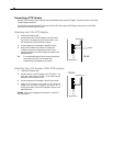
Attaching the 4-Pin Adapter (240H & 480H models)
1. Locate the PTZ adapter cable
2. Connect the wires of the PTZ adapter to the PTZ camera. The
yellow wire should connect to the RX+ on the camera and the
orange wire should connect to the RX-.
3. Connect the other end of the adapter to the DVR as shown.
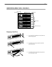
4. Assign the PTZ camera an ID number in PTZ Setup that
coincides with the number assigned to the camera. This is
normally done utilizing a dip-switch configuration method on the
addressable dome.
Example: If the camera is plugged into input number 5, set the PTZ
unit to ID number 5.
RS-422
Signal Line (+)
Signal Line (-)
RS-485
Signal Line (+)
Signal Line (-)
Ground