


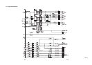
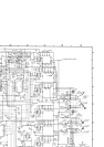
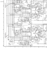
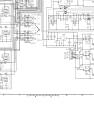
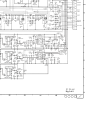
SECTION 3
SERVICING DIAGRAMS
SECTION 3
SERVICING DIAGRAMS
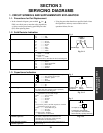
1. CIRCUIT SYMBOLS AND SUPPLEMENTARY EXPLANATION
1-1. Precautions for Part Replacement
• In the schematic diagram, parts marked (ex.
F801) are critical part to meet the safety regulations,
so always use the parts bearing specified part codes
(SN) when replacing them.
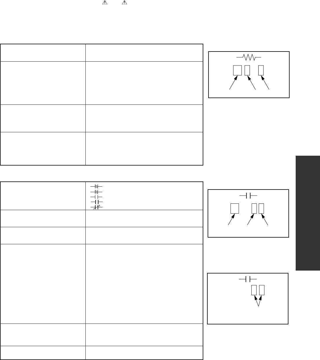
1-2. Solid Resistor Indication
Unit None ...........Ω
K ...........kΩ
M ...........MΩ
Tolerance None ...........±5%
B ...........±0.1%
C ...........±0.25%
D ...........±0.5%
F ...........±1%
G ...........±2%
K ...........±10%
M ...........±20%
Rated Wattage (1) Chip Parts
None .........1/16W
(2) Other Parts
None .........1/6W
Other than above, described in the Circuit Diagram.
Type None ...........Carbon film
S ...........Solid
R ...........Oxide metal film
W ...........Metal film
W ...........Cement
FR ...........Fusible
Symbol
+
...........Electrolytic, Special electrolytic
NP
...........Non polarity electrolytic
...........Ceramic, plastic
M
...........Film
...........Trimmer
Unit None ...........F
µ ...........µF
p ...........pF
Rated voltage None ...........50V
For other than 50V and electrolytic capacitors,
described in the Circuit Diagram.
Tolerance (1) Ceramic, plastic, and film capacitors of which
capacitance are more than 10 pF.
None ...........±5% or more
B ...........±0.1%
C ...........±0.25%
D ...........±0.5%
F ...........±1%
G ...........±2%
(2) Ceramic, plastic, and film capacitors of which
capacitance are 10 pF or less.
None ...........more than ±5% pF
B ...........±0.1 pF
C ...........±0.25 pF
(3) Electrolytic, Trimmer
Tolerance is not described.
Temperature characteristic None ...........SL
(Ceramic capacitor) For others, temperature characteristics are
described. (For capacitors of 0.01 µF and
no indications are described as F.)
Static electricity capacity Sometimes described with abbreviated letters as
(Ceramic capacitor) shown in Eg. 3.
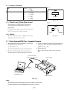
1-3. Capacitance Indication
100k
Rated Wattage Type Tolerance
Eg. 1
104
10x10
4
pF (0.1µF)
Temperature characteristic
(or Temperature characteristic+
Static electricity capacity tolerance)
Eg. 3
100µ
Temperature
response
Rated
voltage
Tolerance
Eg. 2
Fig. 3-1-1
Fig. 3-1-3
Fig. 3-1-2
• Using the parts other than those specified shall violate
the regulations, and may cause troubles such as
operation failures, fire etc.
3-1