


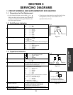
1-4. Inductor Indication
Unit None ...........Η
µ ...........µH
m ...........mH
Tolerance None ...........±5%
B ...........±0.1%
C ...........±0.25%
D ...........±0.5%
F ...........±1%
G ...........±2%
K ...........±10%
M ...........±20%
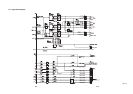
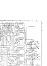
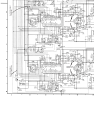
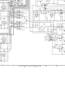
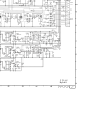
1-5. Waveform and Voltage Measurement
• The waveforms for CD/DVD and RF shown in the
circuit diagrams are obtained when a test disc is
played back.
• All voltage values except the waveforms are expressed
in DC and measured by a digital voltmeter.
1-6. Others
• The parts marked with “NC” or “KETU” in the circuit
diagrams are not used for this model.
Eg. 4
Eg. 5
Fig. 3-1-4
Fig. 3-1-5
Type name
10µ
Type Tolerance
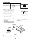
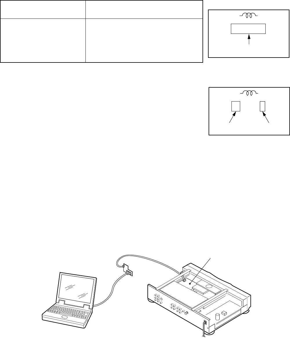
1-7. When Replaced ROM ICs or Upgraded Firmware
1. When replaced the following ROM ICs, it is necessary
to write the data into the new ICs.
1) IC615 (firmware)
2) IC613 (Setup default data and other information)
2. When the firmware is upgraded, rewriting the new
firmware into IC615 may be requested for servicing.
Fig. 3-1-6
Note:
• The firmware and setup data floppy discs are not available as service parts.
For more information, consult TOSHIBA service office in your area.
Computer
(MS-DOS/PC-DOS)
DATA UPDATE KIT
(RS-232C Interface/cable)
DVD video player
RS-232C
cable
MAIN PC Board
3. Connect a computer to the main PC board of the DVD
video player with using DATA UPDATE KIT (P/No.
79080074). (Fig. 3-2-6)
4. Writing operation
Refer to the instruction attached to the data floppy
disc.
3-2