


16
Connections
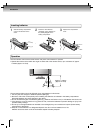
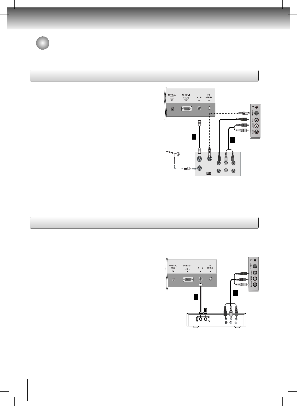
VCR Setup
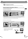
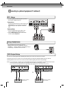
Cable TV Setup
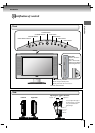
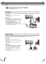
External equipment connections (Continued)
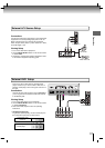
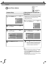
Connection 1
Set VCR CH switch to 3 or 4 and then tune TV to the
same channel number.
Connection 2
1. Connect the audio/video output jacks on the VCR to the
corresponding input jacks on the TV. When connecting the
TV to a VCR, match the jack colors (Video = yellow, Audio
Left = white, and Audio Right = red).
2. Insert a video tape into the VCR and press PLAY on the
VCR. (Refer to the VCR owner’s manual.)
3. Use the INPUT SELECT button on the remote control to
select Video. (If connected to S-VIDEO on the side panel,
select the S-Video external input source.)
75
ANT IN
OUT
IN
CH3 CH4
S-VIDEO
ANT IN
ANT OUT
(R) (L)
AUDIO
VIDEO
1
Typical
Antennas
TV Back Panel
TV Side Panel
VCR
2
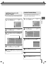
Connection 1
1. Select channel 3 or 4 with the channel switch on the
cable box.
2. Tune the TV channel to the same selected output channel
of the cable box.
3. Select channels at the cable box or with the cable box
remote control.
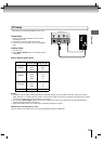
Connection 2
1. Connect the audio/video output jacks on the Cable Box to
the corresponding input jacks on the TV. When connect-
ing the TV to the Cable Box, match the jack colors
(Video = yellow, Audio Left = white, and Audio Right =
red).
2. Use the INPUT SELECT button on the remote control to
select Video.
3. Select channels using the cable box remote control.
TV Side Panel
- After subscribing to a local cable TV service and installing a converter, you can watch cable TV programming.
- For further cable TV information, contact your local cable service provider.
75
ANT IN
TV
VCR
(R) AUDIO (L)
VIDEO
RF Cable
1
Cable Box
2
TV Back Panel
The connection cables are not supplied.