


Installation NOTES
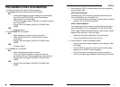
To install the PS-CF-01 series media converter:
1. Connect host signal to PS-CF-01 media converter.
• Locate or build twisted-pair cables that are compliant with
cable specifications (See page 7) and with male RJ-45 plug
connectors installed at both cable ends.
NOTE: Install TRANSITION Networks balun part number: 3-4554
between RJ-45 cable and Twinax connector.
• Install balun at host Twinax connector.
•. Connect male RJ-45 plug connector at one end of twisted pair
cable to balun on host Twinax connector.
• Connect male RJ-45 plug connector at other end of twisted
pair cable to female RJ-45 connector on PS-CF-01 media
converter.
2. Connect PS-CF-01 media converter near host to second PS-CF-01
media converter near terminal device*.
• Locate or build fiber cable that conforms to cable
specifications (See page 7) and with male fiber connectors
installed at both ends.
• Connect one end of first fiber cable to PS-CF-01 media
converter TX connector.
• Connect other end of that fiber cable to second PS-CF-01
media converter RX connector (or to PowerStar™ IV fiber SIC
card RX connector).
• Connect one end of second fiber cable to PS-CF-01 media
converter RX connector.
• Connect other end of that fiber cable to second PS-CF-01
media converter TX connector (or to PowerStar™ IV fiber SIC
card TX connector).
*Or optionally connect directly to PowerStar™ IV fiber SIC card.
CABLE SPECIFICATIONS
The physical characteristics of the cable must meet or exceed the following:
FIBER CABLE
MULTIMODE
Fiber Optic Cable Recommended: 62.5 / 125 µm multimode fiber
Fiber Optic Transmitter Power: min: -19.0
dBm max: -14.0 dBm
Fiber Optic Receiver Sensitivity: min: -32.5
dBm max: -14.0 dBm
Wavelength: 850nM
Bit error rate: ≤10
-9
Maximum Cable Distance: 2 kilometers
SINGLEMODE
Fiber Optic Cable Recommended: 9 µm singlemode fiber
Fiber Optic Transmitter Power: min: -27.0
dBm
max: -17.0 dBm
Fiber Optic Receiver Sensitivity: min: -32.5 dBm max: -13.0 dBm
Wavelength: 1300nM
Bit error rate: ≤10
-9
Maximum Cable Distance: 8 kilometers
TWISTED PAIR CABLE AND CONNECTOR
Category 3 wire or better is required; category 5 wire is recommended. Either
shielded twisted pair (STP) or unshielded twisted pair (UTP) can be used. DO
NOT USE FLAT OR SILVER SATIN WIRE.
Category 3:
Gauge 24 to 22 AWG
Attenuation 28 dB/1000’ @ 10 MHz
Differential Characteristic Impedance 100 Ω ±10% @ 10 MHz
Category 5:
Gauge 24 to 22 AWG
Attenuation 20 dB/1000’ @ 10 MHz
Differential Characteristic Impedance 100 Ω ±10% @ 10 MHz
Minimum UTP/STP Cable Distance: 7.6 meters (25 feet)
Maximum UTP/STP Cable Distance:
762 meters (2500 feet)
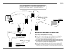
Connector:
RJ-45 connectors with active
pair pins 4 & 5.
7
2
All cable connections to the PS-CF-01 MUST be
AT LEAST 7.6 meters (25 feet) in length.
PS-CF-01
3
4
5
6
RJ-45
connector
Straight Through Cable
3
4
5
6
RJ-45
connector
NOTE: The active pair in a twisted-pair
copper 5250-compliant network are pins
4 & 5. Use only dedicated wire pairs
(such as blue/white & white/blue,
orange/white & white/orange) for the
active pins.