


CABLE SPECIFICATIONS
Fiber Cable
MULTIMODE
Fiber Optic Cable Recommended: 62.5 / 125 µm multimode fiber
Optional: 100 / 140 µm multimode fiber
85 / 125 µm multimode fiber
50 / 125 µm multimode fiber
SGETF1013 850 nM
Fiber Optic Transmitter Power: min: -10.0 dBm max: -4.0 dBm
Fiber Optic Receiver Sensitivity: min: -17.0 dBm max: -0.0 dBm
Link Budget: 7.0 dB
Typical Maximum Cable Distance*: 220 meters
SGETF1018 850 nM
Fiber Optic Transmitter Power: min: -9.5 dBm max: -4.0 dBm
Fiber Optic Receiver Sensitivity: min: -17.0 dBm max: -0.0 dBm
Link Budget: 7.0 dB
Typical Maximum Cable Distance*: 220 meters
SINGLEMODE
Fiber Optic Cable Recommended: 9 µm singlemode fiber
SGETF1014 1300 nM
Fiber-optic Transmitter Power: min: -13.0 dBm max: -3.0 dBm
Fiber-optic Receiver Sensitivity: min: -20.0 dBm max: -3.0 dBm
Link Budget: 7.0 dB
Typical Maximum Cable Distance*: 5 kilometers
SGETF1015 1300 nM
Fiber-optic Transmitter Power: min: -5.0 dBm max: -0.0 dBm
Fiber-optic Receiver Sensitivity: min: -20.0 dBm max: -3.0 dBm
Link Budget: 15.0 dB
Typical Maximum Cable Distance*: 25 kilometers
SGETF1017 1550 nM
Fiber-optic Transmitter Power: min: -3.0 dBm max: -2.0 dBm
Fiber-optic Receiver Sensitivity: min: -23.0 dBm max: -3.0 dBm
Link Budget: 20.0 dB
Typical Maximum Cable Distance*: 65 kilometers
SGETF1025 1550 nM
Fiber-optic Transmitter Power: min: -9.5 dBm max: -3.0 dBm
Fiber-optic Receiver Sensitivity: min: -20.0 dBm max: -3.0 dBm
Link Budget: 20.0 dB
Typical Maximum Cable Distance*: 65 kilometers
*Actual distance dependent upon physical characteristics of network installation.
Copper Cable
Category 5 twisted-pair copper wire is required. Either shielded twisted-pair (STP) or
unshielded twisted-pair (UTP) can be used. DO NOT USE FLAT OR SILVER SATIN WIRE.
CATEGORY 5:
Gauge 24 to 22 AWG
Attenuation 22.0 dB /100m @ 100 MHz
Maximum Cable Distance: 100 meters
The Gigabit Ethernet™ network uses all four wire pairs. The active pairs are pins 1 & 2,
pins 3 & 6, pins 4 & 5, and pins 7 & 8. Use only dedicated wire pairs (such as blue/white
& white/blue, orange/white & white/orange) for the active pins. NOTE: Straight-
through/crossover configuration is automatic.
Install Cable
COPPER
NOTE: The SGETF10xx series media converter auto-negotiation feature
allows the media converter to bring up the copper link in the highest
mode possible for ALL the attached network devices.
1. Locate or build 1000BASE-TX-compliant cables with male RJ-45
connectors installed at both ends.
2. Connect RJ-45 connector at one end of cable to media converter
RJ-45 port connector.
3. Connect RJ-45 connector at other end of cable to 1000BASE-TX-
compliant device RJ-45 port connector.
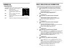
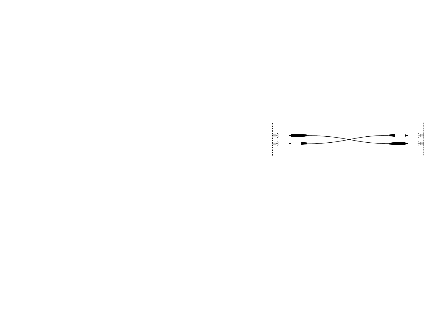
FIBER
1. Locate or build 1000BASE-SX/LX-compliant fiber cable with male
two-stranded TX to RX connectors installed at both ends.
2. Connect cable with connector installed at TX location on media
converter to RX location on attached device.
3. Connect cable with connector installed at RX location on media
converter to TX location on attached device.
Power the Media Converter
1. Install power adapter cord at back of media converter.
2. Connect power adapter plug to AC power.
3. Verify that media converter is powered by observing illuminated
LED(s).
TX
RX
TX
RX