


Page 4
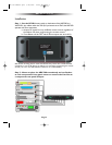
MRF-300 BASE STATION
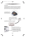
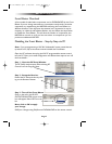
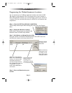
Daisy Chain Multiple MRF-300’s to One RFX-150 RF Sensor
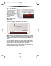
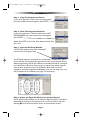
Step 3 - Connect the RFX-150 to the RF IN, but DO NOT MOUNT IT!
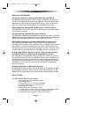
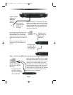
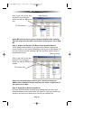
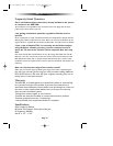
Copper colored
conductor is
GROUND
(Sleeve of
the Plug).
Silver colored
conductor is IR
DATA (Tip of
the Plug).
When connecting to a components rear panel
IR Input, cut the flasher off of the wire, strip the
two conductors and connect to the rear panel
IR Input.The MRF-300 is only compatible with
standard IR Inputs, not proprietary control sys-
tems such as Control S.
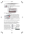
Use the cable with 3.5mm Stereo Mini
plugs on both ends to daisy chain as
many MRF-300’s as you need. Simply
connect the RF OUT of the first to the
RF IN of the next and so on down the
line.
By daisy chaining MRF-300’s, you can
easily control up to 90 identical com-
ponents.
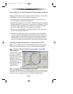
When connecting a single RFX-150 to the MRF-
300 utilize the cable with 3.5 mm plugs on both
ends. When you need a longer wire or are con-
necting up to three RFX-150’s, use the cable
with a plug on one end and tinned ends. These
can be extended as much as 200’, then connect-
ed to the green removable screw connector
(which plugs into the alternate RF IN). The RED
connects to 5V, the WHITE to DATA and the
BLACK connects to GROUND.
Plug the 3.5mm plug
into the RFX-150’s RF
OUT jack.
Connect the other
end of the cable to
one of the two RF IN
on the MRF-300,
RF OUT of the
RFX-150 to the
RF IN of the
MRF-300.
RF OUT of the
first MRF-300 to
the RF IN of the
next MRF-300.
MRF-300 Manual.qxd 1/14/2005 12:40 PM Page 4