


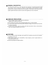

INSTALLATION PRECAUTIONS
Install the unit at the location accessible to the wall outlet easily.
Install the tuner away from high frequency noise generating equipment such as fluorescent lamps
and personal computers, whenever possible.
Avoid installing a receiving antenna in close proximity to the steel frames of the building or lockers.
The clearance between the antenna and the wall needs to be at least 30 cm (1 foot).
ADDITIONAL EXPLANATIONS
1. Squelch Circuit
In a receiver employing only a noise or carrier squelch, the squelch circuit is actuated and provides the
output whenever the receiver receives the same RF carrier as a receiving frequency. This causes
even a disturbing radio signal to be received provided its frequency is the same as the receiving
frequency. As a result, it can happen that sound is suddenly heard from the speaker due to disturbing
radio signal even when the wireless microphone's power switch is left OFF.
The squelch circuit of TOA's wireless systems consists of both the tone and noise squelches, and is
not actuated if only same RF carrier as the receiving frequency is received. It is so designed as to be
actuated and output a signal only when the received RF carrier contains a very exact pre-determined
tone frequency component. Therefore, disturbing radio signals are rejected and the speaker can be
kept completely quiet when the wireless microphone's power switch is set to OFF, ensuring reliable
use in every application.
2. Frequency Indicators
Component frequency ratings are expressed in combinations of alphabetic and numeric
characters, with letters substituted for all numbers to the left of the 1 MHz digit.
For example :
C = 160 MHz
D= 170 MHz
E = 180 MHz
F = 190 MHz
G = 200 MHz
H = 210 MHz
All numbers to the right of the 10 MHz digit are still expressed as numerals.
Therefore : D5432 = 175.432 MHz
G7654 = 207.654 MHz
— 5 —