


Page 6
Series 3 Cameras Installation Instructions
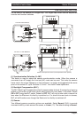
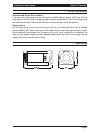
CONTROLS AND SWITCHES
(4) Electronic Iris (EI)
The Electronic Iris (EI) compensates for excessive light level by automatically adjusting the
shutter speed. The electronic iris should be ON when using fixed or manual iris lenses.
When using Auto Iris (AI) lenses of either the video drive or DC drive types the EI must be
OFF. Also see (10) Electronic Iris and DC Lens Level Adjustment Potentiometer.
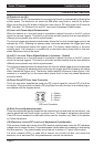
(5) Line Lock Phase Adjust Potentiometer
When the camera is in line-lock mode it is possible to adjust the point on the AC cycle at
which the camera triggers. This facility is provided so that cameras that are connected to
different mains phases may still be synchronised.
The line lock phase adjustment potentiometer allows the line lock phase trigger point to be
adjusted by ±120
O
. Rotating the potentiometer clockwise advances the trigger point and
turning it anticlockwise retards the trigger point. The factory default setting is the zero
crossing point. If all cameras in a system are on the same mains phase then no line lock
phase adjustment should be made.
(6 and 7) Line Lock Phase Adjust Buttons (+ Advance; - Retard)
When the camera is in line-lock mode it is possible to adjust the point on the AC cycle at
which the camera triggers. This facility is provided so that cameras that are connected to
different mains phases may still be synchronised.
The line lock phase adjustment buttons allows the line lock phase trigger point to be adjusted
by ±120
O
. Pressing the advance button advances the trigger point and pressing the retard
button retards the trigger point. The factory default setting is the zero crossing point. If all
cameras in a system are on the same mains phase then no line lock phase adjustment
should be made.
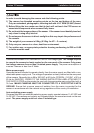
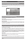
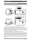
(8) Direct Drive/DC Drive Lens Connector
This 4-pin connector supplies the power and DC control signal for use with DC drive Auto
Iris lenses. If the lens does not have a DD plug fitted then wire the lens to a suitable plug in
accordance with the diagram below:
1 = Damp -
2 = Damp
+
3 = Drive +
4 = Drive -
1
3
2
4
DD L
e
n
s
C
onn
ec
tor
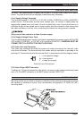
(9) Back Focus Adjustment screws
These two adjustment points located on the camera body top and side (top not shown), are
used to adjust the back focal length or picture focus. The range of adjustment allows both
C and CS mount lenses to be used without the need for a spacer ring. Refer to the section
on Focus Adjustment
(10) Electronic Iris and DC Lens Level Adjustment Potentiometer
If the camera is used with a direct drive (DD) lens this potentiometer varies the DC reference
voltage used to control the lens. The potentiometer has the effect of increasing or decreasing
the lens aperture. This potentiometer should be set to obtain a 1V pk-pk video output.
If a mono camera (VPM..) is used with a manual iris or fixed iris lens, and hence the
electronic iris is switched ON, this potentiometer controls the electronic