


Page 7
Installation Instructions Series 3 Cameras
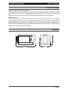
CONTROLS AND SWITCHES
iris level. The potentiometer is factory set to give a 1V pk-pk video output for a typical
scene. The level should not be adjusted unless absolutely necessary.
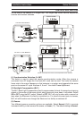
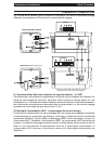
(11a) Supply Voltage Terminals
This terminal accepts 11-40 VDC or 14-30 VAC at 50Hz (CCIR/PAL) or 60Hz (EIA/NTSC)
power source. The terminals are the quick release type. To connect a cable press the
appropriate release lever and insert the end of cable fully home. Ensure that there is a
sufficient length of bare tinned wire to make contact with the connector. Also ensure that
the cable insulation is not too thick, preventing the cable from being properly inserted.
Only connect the camera to a class 2 power supply.
(11b) Supply Voltage Power Cord
The non-detachable power supply cord must be connected to a power supply of 98 to 260
VAC at 50Hz (CCIR/PAL); or 110 VAC ±10% at 60Hz (EIA/NTSC). CAMERAS MUST BE
CONNECTED TO A PROTECTIVE EARTH GROUND.
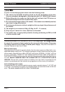
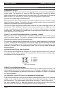
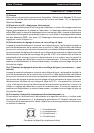
(12) Video Iris Lens Connector
This three way connector provides the power and video drive signal for use with video
drive Auto Iris lenses. The terminal block that mates with this connector is provided in the
packing kit. Connect the lens to the terminal block in accordance with the diagram below:
+
V
= Lens positive supply
= Lens ground
= Video drive signal
+
V
A
u
to Iri
s
L
e
n
s
C
onn
ec
tion
s
(13) Video Output BNC Connector
To obtain a 1.0V [pk-pk] composite video signal, connect a video coaxial cable terminated
with a 75 Ohm BNC connector to the BNC socket marked VIDEO OUT.
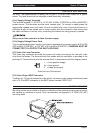
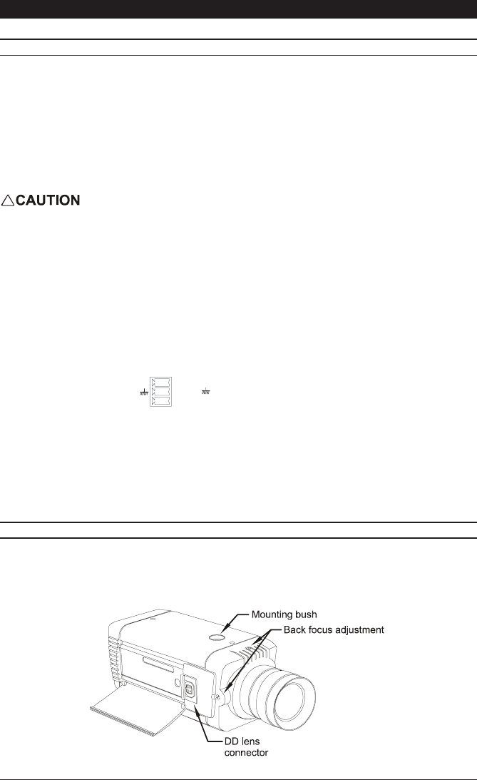
CAMERA MOUNTING
Mounting points are provided on the top and bottom of the camera and are used to mount
the camera on a bracket or tripod. Only use standard, photographic 1/4 BSW (20 UNC)
mounting bolts.