


9
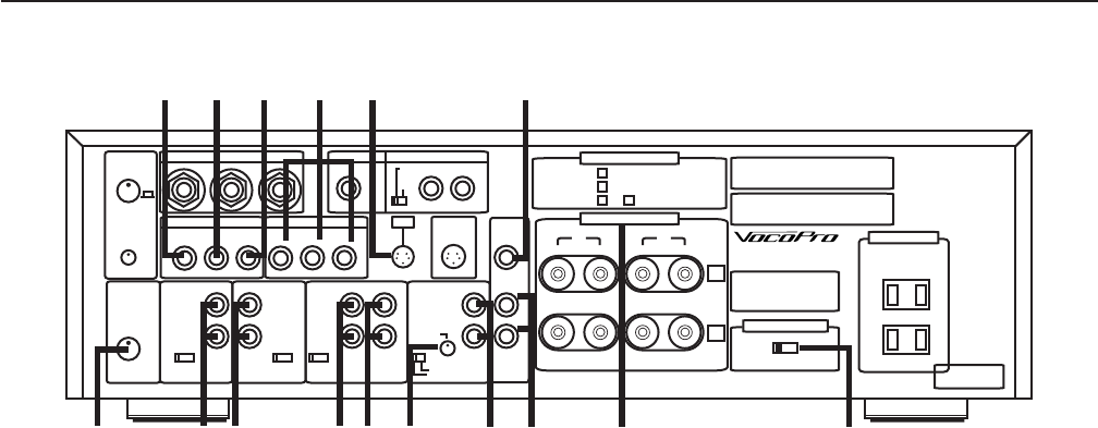
Rear Panel Descriptions
SONIC
ENHANCER
REAR MIC INPUT
VIDEO IN VIDEO OUT
BGV DVD AUX
L
R R
L L
R R
L
1 2 3
MIC-OUT
MONO
INTERNAL
EXIT
GND
REMOTE IN
(MONO) L
MONO
SPEAKER IMPEDANCE
SPEAKER SYSTEM
CAUTION:FOR CONTINUED PROTECTION AGAINST
FIRE HAZARD, REPLACE ONLY WITH SAME TYPE FUSE.
110-220V~18.A 250V.
220-240V~T4A 250V.
KARAOKE AMPLIFIER
11-220V/220-240V~50/60HZ
POWER CONSUMPTION:175W
MAX POWER CONSUMPTION: 690W
LA VERNE CALIFORNIA
U.S.A
CAUTION:SHOCK HAZARD, DO NOT REMOVE SCREWS.
ATTENTION: RISQUE DE CHOC ELECTRIQUE.
NE PAS ENLEVER LES VIS.
VOLTAGE SELECTOR
220-240V ~110-120V~
AC OUTLETS
SAME AS LINE VOLTAGE
UNSWITCHED 300W
MAX TOTAL
MADE IN TAIWAN
www.vocopro.com
R
+ -
L
R R
L
R L
MIC-RETURN-IN
INPUT
LEVEL-ADJ
ON
MIC B IN
L M H
AUTO F LEVEL
DVD IN AUX IN
AUDIO
SERIAL NO.
L M H
AUTO F LEVEL
TAPE IN TAPE
(MUSIC BYPASS)
STEREO
MONO
MIN MAX
INPUT
LEVEL
BGM IN PRE-OUT
SYSTEM
1
1
2
2
SYSTEM
SYSTEM
AND
:MINIMUM 4 HOMS
:MINIMUM 4 HOMS
:MINIMUM 8 HOMS
L M H
AUTO F LEVEL
(LINE LEVEL)
MIN MAX
1
2
- +
1
2
3
4
5
6
7
8
9 10
11 12
13
14
15
16
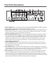
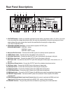
1. VOLTAGE Selector – Before you amplifier is shipped from the factory, the switch is set to 110-120V. If you move
to an area where the voltage requirements differ, set under the responsibility of the user according to the local
power voltage. Be sure to replace the fuse with the specified after changing the voltage setting.
(110-120V~7A 220-240~3.5A)
2. SPEAKER SYSTEMS Terminals – Connect with the speaker OUTPUT jacks.
SPEAKER IMPEDANCE SYSTEM 1: 4-ohm
SYSTEM 2: 4-ohm
SYSTEM 1 AND 2: 8-ohm
3. Monaural Pre-Out Jacks – Connect with the INPUT jacks of a powered monitor speaker etc.
4. VIDEO Output Jacks – Connect with the video INPUT of the monitor TV.
5. AUX Video Input Jack – Connect the video OUTPUT jack of an external video player to this jack.
6. DVD Video Input Jack – Connect the video OUTPUT jack of the player to this jack.
7. BGV Input Jack – Connect the video OUTPUT jack of the background video player, video camera, etc., to
this jack.
8. Microphone B Input Jacks – Connect the OUTPUT jack of the wireless microphone receiver.
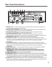
9. DVD Input Jacks – Connect the OUTPUT jacks of the player to these jacks.
10. AUX Input Jacks – Connect the OUTPUT jacks of the Source to these jacks.
11. TAPE Input jacks – Connect the OUTPUT jacks of the TAPE deck to these jacks.
12. TAPE Output Jacks – Connect the INPUT jacks of the TAPE deck to these jacks.
13. BGM Input Jacks – Connect the OUTPUT jacks of the BGM device (cable broadcasting) to these jacks.
14. PRE-OUT Output Jacks – Connect the INPUT jacks of the extension Power amplifier or the Mixer
to these jacks.
15. BGM (Background Music) Input Level Control-Adjust this control to optimize the BGM input level.
Note that the BGM level cannot be varied by the MUSIC VOL. control on the front panel.
16. GROUND Terminal – The grounding wire to be connected to a grounding line is connected here.