


99 Ling Road . Rochester, NY 14612 . Phone 585 663-8820 . Fax 585 865-8930 . Email: sales@whirlwindusa.com . http://www.whirlwindusa.com
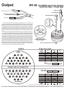
Output
Check for proper wire strip length by pushing wire into a contact and
looking to see the wire strands through the hole in the side. Load the contact
into the crimp tool locator and push the wire into place. Squeeze the handles
while making sure that the wire stays in the wire hole . The crimper is a full cycle
racheting type and can only be released by completing the cycle, at which
point the crimp contact will pull freely from the tool. Inspect the connection and
continue, following the color code to apply pins and sockets to the proper wire
pairs.
Load the pins and sockets into the insert housing according to the pin out
color code. Contacts are inserted into the hard plastic wafer and pushed into
place with the red handled end of the insertion tool or small needle nose pliers.
Fully inserted contacts are locked in place by spring metal retention clips
embedded in the plastic wafer. In the event a contact must be removed from
the insert use the white handled, extraction end of the contact tool. Carefully
slip the tool into the plastic wafer until the small hole in the end of the extractor
is even with the surface of the wafer. Do not force the tool in as it is easily
deformed. Only when the tool is properly seated will the spring fingers release,
allowing the contact to be removed. If the wire is still attached, gently pull the
wire to remove it. If the wire is broken, push the contact from the rubber face
side with an opposite contact until it is exposed in the back.
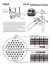
PIN
W5 48
Pin MASS Connector System
Technical Data - Crimp Type
White EXTRACTION
Red INSERTION
Tip
Push from opposite side to remove
Make sure Contact
and Wire are fully inserted
before crimping
Crimp
AMP 91067-2
Inspection Hole
1 2 3
5 6 7 8 94
13 14 15 16121110
21 22 23 2420191817
16 16 16
G
14 14 12 12 1214
G G
4 2 2 24466
G G
21 22 23 2420191817
13 14 15 16121110
5 6 7 8 94
1 2 3
10 8 810106
G GG
10 810106
GG
9 7 7 7995
G GG
13 13 11 11 1113
G G
15 15 15
G
3 1 1 13355
G G
PINS
SOCKETS
WIRING SIDE OF CONNECTOR
16 Pair Color Code
2
4
6
8
10
12
14
16
GREEN
RED
RED
RED
BLACK
BLACK
BLACK
BLACK
BLUE
ORANGE
YELLOW
GREEN
ORANGE
YELLOW
GREEN
RED
15
13
11
9
7
5
3
1
BLACK
BLACK
BLACK
RED
RED
RED
GREEN
GREEN
WHITE
BLUE
BROWN
WHITE
BLUE
BROWN
WHITE
YELLOW
PIN
SOCKET
OUTPUT
XLR
Pin 3 Pin 2 Pin 1
G
Pair #
XLR
Pin 3 Pin 2 Pin 1
G
Pair #