


2
1. Shut off power to the unit and install Lock-Out tag on all
disconnects and breakers.
2. Turn off main gas supply line valve.
3. Mark all wires going to the old valve with the terminal
description that they are attached to.
4. If replacing an existing valve, disconnect all plumbing and
electrical connections from the old control.
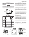
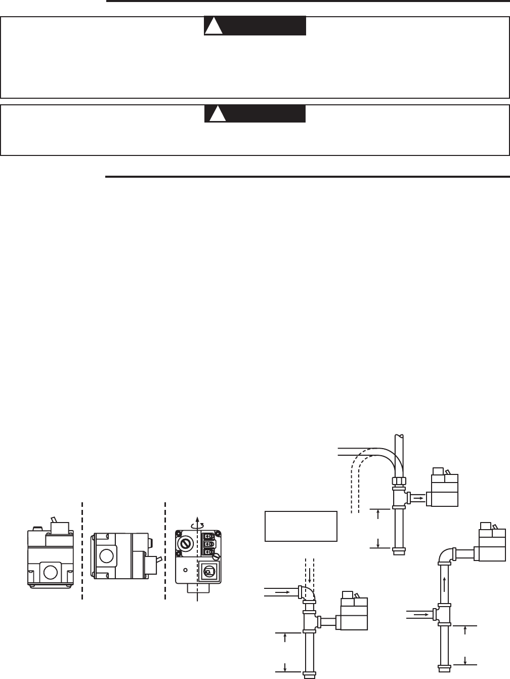
5. The control may be installed in any orientation except
upside down (see figure 1). The arrow on the valve indi-
cates the direction of gas flow through the control.
6. You should use new pipe that is properly chamfered,
reamed, and free of burrs and chips. If you are using old
pipe, be sure it is clean and free of rust, scale, burrs,
chips, and old pipe joint compound.
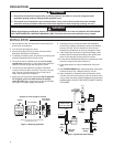
7. Apply pipe joint compound (pipe dope) that is approved
for all gases, only to the male threads of the pipe
joints. DO NOT apply compound to the first two threads
(see figure 2 for typical piping connections).
PRECAUTIONS
INSTALLATION
1. Do not short out terminals on gas valve or primary control to test. Short or incorrect wiring can cause
equipment damage, property damage and/or personal injury.
2. This control is not intended for use in locations where it may come in direct contact with water. Suitable
protection must be provided to shield the control from exposure to water (dripping, spraying, rain, etc.).
CAUTION
!
Before beginning any modification, be sure ALL electrical disconnects are in the OFF position. TAG THE DISCON-
NECT SWITCHES WITH A SUITABLE WARNING LABEL. Electrical shock can cause personal injury or death.
WARNING
!
Horizontal
Drop
Piped Gas
Supply
Gas Valve
3 in.
minimum
Gas Valve
Riser
Piped Gas
Supply
3 in.
minimum
Drop
Horizontal
Riser
Gas Valve
Tubing Gas
Supply
3 in.
minimum
NOTE:
Always Include
A Drip Leg In Piping
Figure 2. Typical Gas Valve Piping
8. Install gas valve by holding inlet boss with adjustable
wrench. Do not tighten excessively, as this may damage
the valve (Torque: 375 in-lb maximum). Do not cross-
thread during installation as this may damage the valve.
9. If the original gas valve has a barbed hose fitting, install
pressure tube on barbed hose fitting of the replacement
valve. Ensure that the pressure tube will not kink.
10. Do not remove barbed hose fitting from replacement valve
even if the original valve does not have it.
11. Some applications will require modification of the pilot
tube.
12. See SYSTEM WIRING when making electrical connections.
Connect wires per Fig. 3 Diagram and Fig. 4 Chart.
13. After installation is complete, check the operation of the
unit and, with main burners firing, check all joints for leaks
using a soap and water solution. Retighten all joints where
bubbles appear. DO NOT USE OPEN FLAME TO CHECK
FOR LEAKS
INLET BOSS
UP OR DOWN
UPRIGHT
LEFT OR RIGHT
Upright, 90° from upright or vertical
NOTE: Control shown may not be identical
to replacement control.
Figure 1. Mounting positions