


3
INSTALLATION
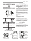
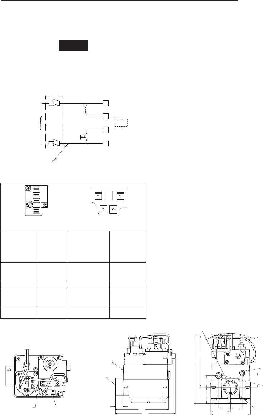
Figure 5. Gas Valve, Top Figure 6. Gas Valve, Side Figure 7. Gas Valve, Outlet Side
1/4” X 3/16”
TERMINAL
ADAPTER
PILOT ADJUSTING
COVER SCREW
.58
4.53
4.00
INLET 1/2"-14 N.P.T.
THDS. WITH SCREEN
INLET
1/8"-27 N.P.T.
PRESSURE TAP
4.00 R
SWING RADIUS
BARBED HOSE FITTING
MUST BE REINSTALLED
IF REGULATOR
IS READJUSTED
PRESSURE ADJUSTING
SCREW IS BENEATH
THE BARBED
HOSE FITTING
OUTLET
PRESSURE TAP
1/8”-27 N.P.T.
PILOT GAS OUTLET
CONNECTION
FOR 1/4” O.D. TUBE
OUTLET 3/4”-14 N.P.T.
THDS. WITH SCREEN
.88
1.44
2.87
1.25
5.09
3.89
REF.
.89
1.08
.88
Pilot Gas Connection
Install fitting into pilot gas outlet (see Fig. 7), turning until finger-
tight. Insert clean, deburred tubing all the way through the fitting.
While holding the tubing securely, slowly tighten fitting until you
feel a slight "give." Tighten the fitting an additional 1-1/2 turns.
Conversion from Natural to L.P. Gas. Refer to conver-
sion kit installation instructions.
Outlet Pressure Adjustment
This control is shipped from the factory with the regulator set to
3.5" W.C. (Natural gas full flow). If required, the regulator can
be adjusted for outlet pressures normally ranging from 2.5 to
5" W.C. (natural gas) or 7.5 to 12" W.C. (L.P. gas). Do not force
the adjusting screw beyond the limits that it can easily be
adjusted.
Inlet/Outlet pressure test ports are 1/8" NPT (see Fig. 7). For
testing pressure, the outlet pressure tap plug will need to be
removed and a separate hose fitting installed. After testing pres-
sure with a manometer remove hose fitting and re-install plug.
Tighten to 60 in-lb max.
1. Attach the manometer to the outlet pressure tap of the
valve.
2. Energize system to ignite main burner.
3. Remove barbed hose fitting.
4. To DECREASE outlet pressure, turn the adjusting screw
(beneath the barbed hose fitting) counterclockwise.
To INCREASE outlet pressure, turn the adjusting screw
clockwise.
5. Replace the barbed hose fitting. Cycle the valve two or
three times to verify regulator setting.
Pilot Gas Adjustment
This control was factory preset and will not normally require
additional adjustment of pilot flame.
If the pilot flame requires adjustment, remove the pilot adjusting
cover screw and gasket (see Fig. 5). To REDUCE pilot flame,
turn the pilot adjust screw (beneath the cover screw) clockwise.
To INCREASE pilot flame, turn the pilot adjust screw counter-
clockwise. Replace gasket and tighten cover screw.
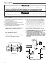
Figure 3. Valve Wiring
PILOT
(REDUNDANT)
C
MAIN
PRESSURE
SWITCH
ON/OFF
SWITCH
2
1
4
3
FLAME
SWITCH
36C
ELECTRICAL SCHEMATIC
36C94-303
VALVE WIRING
Figure 4. Terminal Connection Old/New
36E93-301
36E93-302
36E93-303
36E93-304
Old Terminals
Description Term and Size
36C94-303
36C94-302
New Terminals
5
Pilot
(Redundant)
Coil
1/4" Male Spade 3
1 Main Coil 1/4" Male Spade 1
4
Pressure
Switch
1/4" Male Spade
with 1/4" x 3/16"
adapter installed
4
2
3
Common 1/4" Male Spade 2
1
2
3
4
PILOT ADJ.
5
1
4
3
2
36E93
Terminal Panel
36C94
Terminal Panel
SYSTEM WIRING
REFER TO AND FOLLOW THE APPLIANCE MANUFACTUR-
ER'S WIRING DIAGRAM. REFER TO FIG. 3 FOR TERMINAL
IDENTIFICATION.
NOTE
All wiring should be installed in accordance with local and na-
tional electrical codes and ordinances.
Always check that the electrical power supply used agrees with
the voltage and frequency shown on the gas control.