


2
Test Pins
The pins labeled TEST can be used to change operation
mode in the field. Momentarily short the test pins to force the
system into the defrost mode. Momentarily short the test pins
again to terminate the defrost mode. To avoid unnecessary
system mode transition, do not use the test pins frequently.
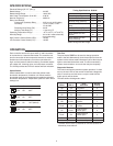
Diagnostic Features
The control continuously monitors system operation. If a fault
occurs, the two LEDs on the control will indicate a diagnostic
code, if more than one fault occurs, only the code with the
higher priority will be shown.
The table shows the diagnostic codes.
SPECIFICATIONS
Electrical Ratings [@ 77
o
F (25
o
C)]:
Rated Voltage ........................ 24 VAC
Rated Voltage Range .................. 18-30 VAC
Max. Power Consumption @ 24 VAC ..... 4.08 VA
Nominal Frequency.................... 50/60 Hz
Relay Load Ratings:
Compressor Contactor Relay ...... 0 VA in rush, 6 VA holding
Fan Relay...................... 1/2 HP @ 240, 1/4 HP
@ 120 VAC
Reversing Valve Relay (RV) ........ 24 VA
Auxiliary Heat Relay (D)........... 1 Amp. 0.6 P.F.
Operating Temperature Range ........... -40
o
to 150
o
F (-40
o
to 65
o
C)
Humidity Range ...................... 5% to 95% relative humidity
(non-condensing)
High Pressure Cutout Switch (HPC)....... 18 VAC
Low Pressure Cutout Switch (LPC) ....... 18 VAC
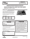
Timing Specications @ 60Hz*
Nom Units
Defrost Lockout Time 34 Mins.
Maximum Defrost Time 14 Mins.
Transient Delay (Normal) 2 Mins.
Back to Back Transient
Delay 4 Mins.
Maximum Frosting Time 6 Hrs.
Short Cycle Lockout Time 5 Mins.
Noise Abatement Time
(Normal 30 Sec.
Noise Abatement Time
(Forced Defrost) 5 Sec.
*50Hz Timings are 20% longer.
LED #1 LED #2
Fault
Indication
Display
Priority
Off Off No power 0
On On Coil sensor failure 4
Off On
Ambient sensor
failure 3
Flash* Flash* Normal 1
Off Flash*
Low pressure
lockout 7
Flash* Off
High pressure
lockout 8
On Flash*
Low pressure
switch open 5
Flash* On
High pressure
switch open 6
On Off Defrost mode 1
Alternating Flash 5-minute delay 2
* The flash time is to be 0.5 seconds on and 0.5 seconds off
followed by 2 seconds off.
OPERATION
Each controller has 24 VAC input and B, Y, and D terminals
for connection to a standard thermostat. The controller has
pins for connection of two temperature sensors to measure
ambient and coil temperature, as well as connections for
high- and low-pressure switch monitoring. Controlled outputs
are outdoor fan, reversing valve, and compressor contactor.
The 47D43 provides two LEDs for status and fault indication.
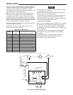
Option Switch
Switch labeled SW1 is used to select the defrost mode
termination temperature of outdoor coil. Defrost mode is
terminated when the coil temperature exceeds the selected
termination temperature. Temperature options for SW1 switch
settings are:
B A
On Off 50
o
F
Off On 60
o
F
On On 70
o
F
(default)
Off Off 80
o
F
B A
B A
B A
B A