


3
INSTALLATION
NOTE
All wiring should be installed according to local and national
electrical codes and ordinances.
The 47D43-811 control may be mounted on any convenient
surface using the six standoffs provided.
The control must be secured to an area that will experience
a minimum of vibration and remain below the maximum
ambient temperature rating of 150
o
F. The control is approved
for minimum ambient temperatures of -40
o
F.
Any orientation is acceptable.
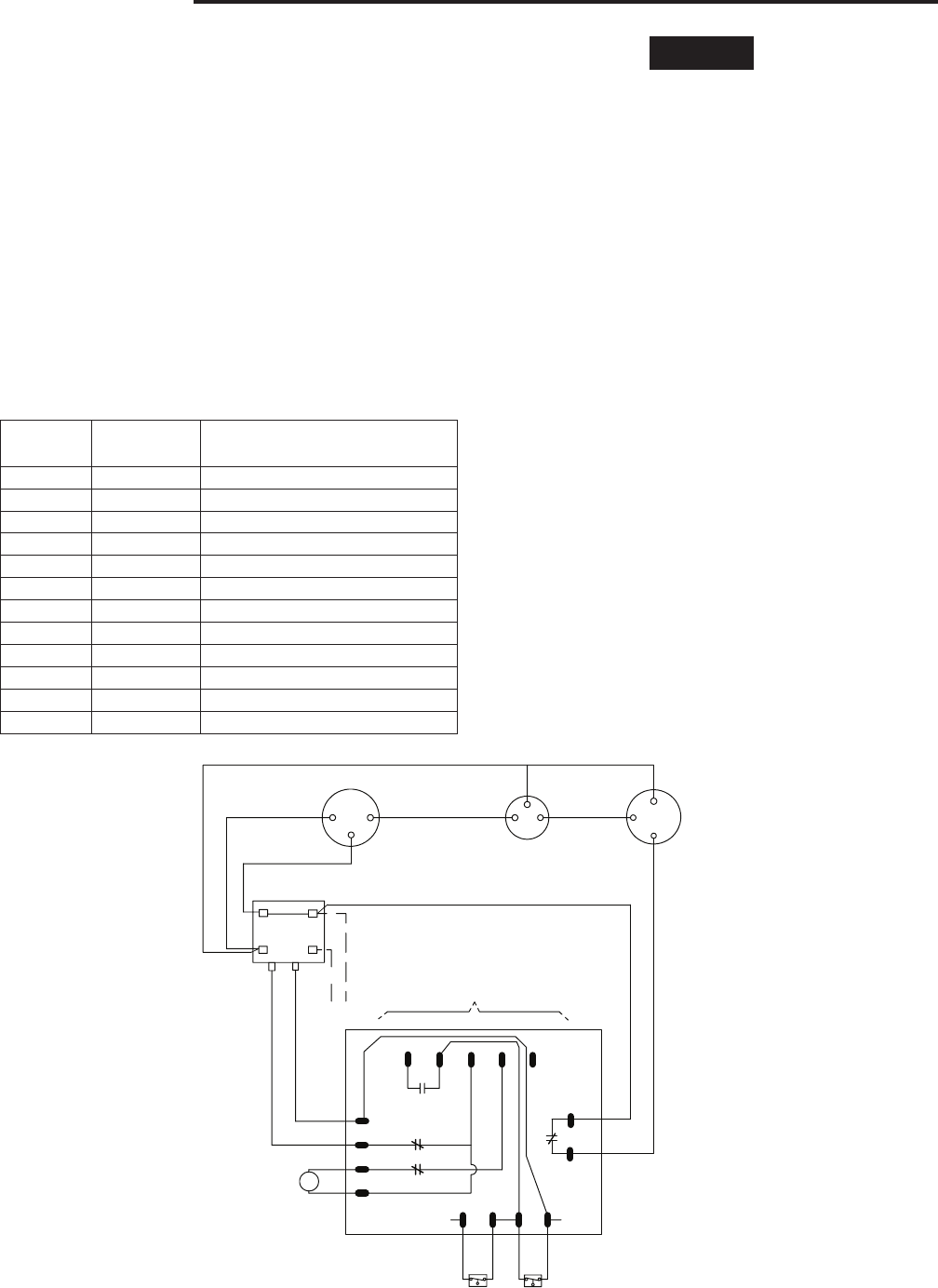
Refer to the wiring diagram and wiring table when connecting
the 47D43-811 control to other components of the system.
UL approved, 105
o
C rated 18 gauge min., stranded 2/64”
thick insulation wire is recommended for all low voltage safety
circuit connections.
UL approved, 105
o
C rated 16 gauge min., stranded 2/64”
thick insulation wire is recommended for all line voltage
connections.
Following installation or replacement, follow appliance
manufacturer’s recommended installation or service
instructions to insure proper operation.
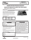
On some units, the Outdoor Ambient Temperature (OAT) and
Outdoor Coil Temperature (OCT) sensors may be attached
permanently to the controller. The 47D43-811 includes
replacement OAT and OCT sensors that plug onto the 2- and
3-pin connectors on the controller board.
Before removing the old controller, note the location of the
OCT sensor on the outdoor coil. The new sensor should
be attached to the coil in the same location, or as close as
possible. The OAT sensor is typically 24-48” long, although
some controllers have the sensor on the board. Placement of
the OAT sensor is not as critical as the OCT sensor, but both
sensors are required for the controller to operate.
Six metal standoffs, 0.375 inch long, are used to support and
mount the control into the unit.
Board size is 3.375 in. x 3.625 in. and requires 1 inch of
headroom (not including mounting).
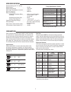
Typical System Wiring Table
47D43
Terminal Type System Component Connection
C 0.25” QC Reversing valve common
RV 0.25” QC Reversing valve output
HPC (2) 0.25” QC High pressure cutout switch
LPC (2) 0.18” QC Compressor call output
CC 0.25” QC Compressor contactor coil
Fan (2) 0.25” QC Outdoor fan control
C 0.25” QC Common, 24 VAC return
R 0.25” QC 24 VAC input
D 0.25” QC Defrost output
Y 0.25” QC Compressor call input
OAT 2-pin connector Outdoor ambient temperature sensor
OCT 2-pin connector Outdoor coil temperature sensor
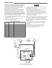
Fig 1. Typical System Wiring Diagram
LPC
HPC
REVERSING
VALVE
FAN
Yout
RV
FAN
C
RV
CC
D
K2
K2
Y
C
B
R
K1
COMPRESSOR
CONTACTOR
TO THERMOSTAT
RUN CAPACITOR
COMPRESSOR
OUTDOOR
FAN MOTOR
HERM FAN
L1
L2
C
LOW
PRESSURE
CUT-OUT
HIGH
PRESSURE
CUT-OUT
R
S
C
S
R
C
CC
K3
To µP
To µP