2
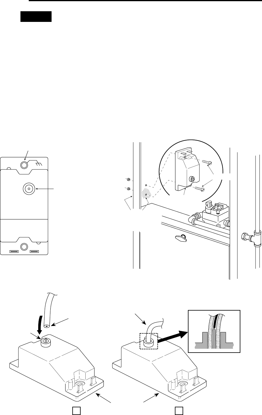
Grounding hole
(indicated by
ground symbol
on 5059 control)
Mounting screws
Note: To ensure
a positive ground
connection, scrape
painted area on both
sides of furnace
Figure 2. Installing the 5059 control
T1 T2
WHITE-RODGERS DIV.
EMERSON ELECTRIC
O
H
I
G
H
V
L
T
A
G
E
C
A
U
T
I
O
N
Grounding hole is identified
with chassis ground symbol
1
⁄
4
” spike
terminal
Figure 1. 5059 Pilot Relight
Control (top view)
INSTALLATION
This control requires a connection to a dead metal
ground for proper control operation (mounting screws
provided accomplish this requirement). When used in a
grounded secondary circuit, T2 terminal must be con-
nected to ground.
Some furnace manufacturers paint their furnaces. If so,
the paint must be scraped from both sides of a furnace
where the grounded mounting hole (identified by a chas-
sis ground symbol on the 5059 pilot relight control) comes
in contact with the furnace wall (see figs. 1 and 2). To
ensure a positive equipment ground, make a final continu-
ity check between the control grounding hole and the
furnace using an ohmmeter.
INSTALL THE 5059 CONTROL
Mount the control inside the furnace in a position so that
you have enough high voltage spark wire to reach the
electrode, but not to expose the control to excessive high
temperature conditions caused by the burner flame. The
5059 control can be mounted directly onto the furnace or
can be mounted on a standard 2” x 4” switch box.
The 5059 control has a
1
⁄4” (interior) diamter terminal with
a ribbed spike. To connect a high voltage wire, cut the end
of the wire flush, to make a flat surface at the wire end.
Then push the wire end securely into the spike terminal to
ensure a proper connection (see fig. 3).
NOTE
1
⁄4” spike terminal
Cut wire flush to
create a flat surface
5059 Pilot Relight Control
Figure 3. Installing the high voltage wire
A
B
Push high voltage wire
onto spike; see inset
Cross-section of spike
connector with high voltage
wire inserted


