


3
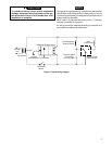
120 VAC
Line
24 VAC
Transformer
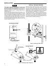
Through
Mounting Hole
To Electrode
5059 Pilot Relight Control
Pilot Redundant
Solenoid Valve
Pressure Switch
in Pilot Gas
(normally open)
Main
Valve Relay
Mercury Flame
Switch Sensor
H
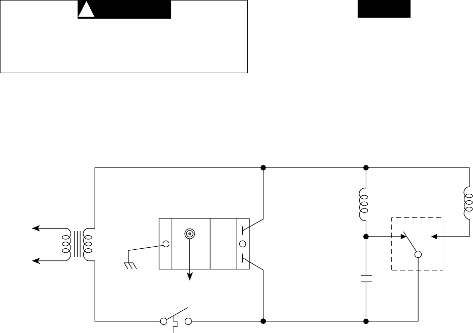
Figure 4. Typical wiring diagram
C
Thermostat
Switch
To prevent electrical shock and/or equipment
damage, disconnect electrical power to the sys-
tem at the main fuse or circuit breaker box, until
installation is complete.
CAUTION
!
The typical wiring diagram (fig. 4) shows only the terminal
identification and wiring hook-up. Always refer to wiring
instructions provided by the equipment manufacturer for
system hook-up operation.
When used in a grounded secondary circuit, T2 terminal
must be connected to a ground.
All wiring should be installed according to national and
local electrical codes and ordinances.
NOTE