


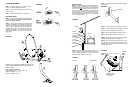
STEP 2. Attach the mount foot to wall (roof, mast, etc.,)
making sure that the mount foot is vertical (90
o
). See
Figure 4. Attach ground wire to mount foot (wrap wire
between bolt/lag screw and mount foot).
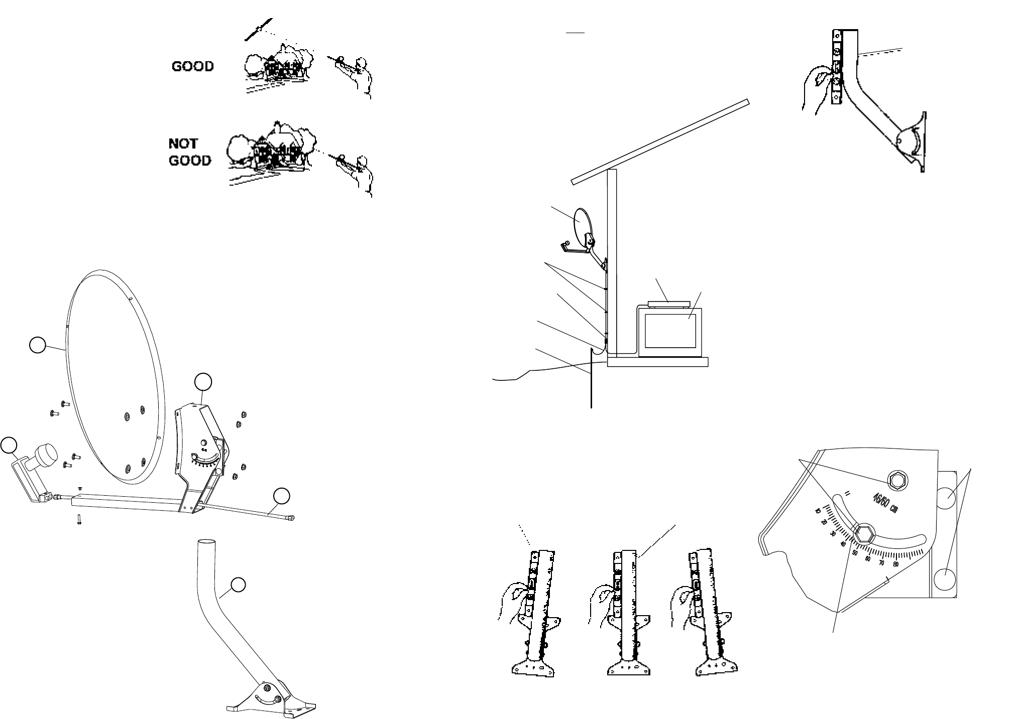
STEP 3. Adjust mount pipe so that it is plumb vertically.
See Figure 5.
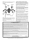
STEP 4. Set antenna onto mount pipe. See Figure 1.
STEP 5. Feed coaxial cable(s) up through the mount
pipe and through the LNBF feed. See Figure 1.
STEP 6. Attach coaxial cable(s) to LNBF. See Fig. 1.
STEP 7. Attach LNBF to antenna. See Figure 1.
STEP 8. Set elevation on antenna; align colored edge
of clamp with degree marking. See Figure 6.
STEP 9. Run coax cable to point where you plan to
enter the house. Be sure to secure the cable so that
it will not ap in the wind (Cable Clips Model SW-0030
are ideal for this task).
INSTALLATION
STEP 1. After conrming that you have a clear line-of-
sight from where you wish to mount the antenna, you
must determine how you are going to mount the antenna
and run your coax downlead to your receiver. Figure 3
shows a typical home installation. As indicated in the
gure, you must ground both the antenna and the coax
downlead before it enters your home. You can order all
the accessories through Winegard or they can be found
at most hardware stores.
FIGURE 3
D
FIGURE 1
FIGURE 2
NOT GOOD CORRECT NOT GOOD
90
o
Vertical
6" Level
FIGURE 4
90
o
VERTICAL
FIGURE 5
FIGURE 6
Elevation
Bolts
Azimuth
Angle
Bolts
ANTENNA ASSEMBLY
STEP 1. Assemble antenna as shown in Figure 1,
except for LNBF and base/tube assembly.
STEP 2. Feed coaxial cable(s) through feed arm as
shown in Figure 1.
STEP 3. Attach LNBF to feed arm. See Figure 1.
SITE SELECTION
STEP 1. Using the digital satellite receiver determine
your azimuth (direction) and elevation. Refer to receiver
manual to perform this step.
STEP 2. After you have determined your azimuth and
elevation step outside to nd the best location for the
antenna. You will need a compass and a protractor or
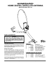
another means of determining elevation. Remember
that the antenna must have a clear line-of-sight to the
satellites. See Figure 2. The satellite signal will NOT
travel through buildings, heavy tree cover and other
obstructions.
Align locating edge
with look angle value
(38° shown)
NOTE: The DS-4248/DS-3118 satellite dish and LNB are
compatible with the DISH
®
DISH 300 system and DIRECTV
®
satellite systems.
This unit may be used with:
DISH Satellites: 61.5
o
, 110
o
, 119
o
, 129
o
, 148
o
DIRECTV Satellites: 101
o
, 119
o
Bell TV™ Satellites: 82
o
, 92
o
[3]
[4]
E
A
[2]
B
[1]
[2]
C
Antenna
SW-0030
Cable Clips
GB-8100 (single)
GB-8200 (dual)
Ground Block
GK-4025
Ground Wire
GR-0004
Ground Rod
Receiver
TV