


RoadStar Antenna RoadStar Antenna
Mounting Option 2
1.
2.
3.
4.
5.
6.
7.
8.
9.
10.
11.
Mounting Option 2, Cont.
12.
13.
14.
15.
16.
17.
18.
19.
20.
5 6
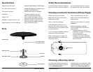
If installing the antenna so that the cable enters the vehicle via a cable entry
plate (sold separately), follow the steps below for Mounting Option 2.
Run coaxial cable from the power supply to the antenna via the cable
entry plate. The antenna needs to be at least 8 inches from the cable
entry plate. Do not fasten the coaxial cable at this point because
additional coaxial cable is required later (see step 18).
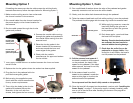
Place the circular gasket in the chosen location for the antenna, and trace
around the outer edge of the gasket.
Check with the vehicle manufacturer for approved sealant for the vehicle.
Then, apply a liberal amount of sealant in the traced circle.
Replace the circular gasket where the
sealant has been applied.
Run the coaxial cable upward through
the antenna pedestal. Make sure the cable
runs through the slot on the underside of
the pedestal.
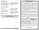
Connect the coaxial cable running
through the pedestal to the
coaxial cable running from the
antenna head.
Before using the supplied screws,
check with the vehicle manufacturer
for any screw requirements.
Then, align the holes in the circular
gasket and pedestal. Mount the
assembly to the roof with four
screws, and tighten the four screws.
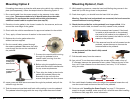
Gently push the cable slack downward through the pedestal, and pull the
cable through the slot.
Twist the antenna head back and forth while pushing it onto the pedestal.
The pedestal should engage with the snap ring inside the antenna head.
While applying pressure, rotate the head until feeling the grooves in the
head line up with the grooves in the pedestal.
Push down again; you should hear the head click into place.
Warning: Once the head and pedestal are connected, the head cannot be
removed without incurring damage.
Check that the scribe line on the pedestal is no longer visible. If the
scribe line is still visible, the head is not fully seated on the pedestal.
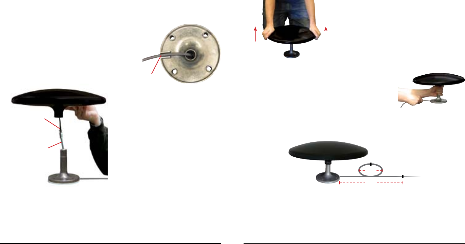
Pull the antenna head upward. If the head
is unable to slide upward on the pedestal,
the head is fully seated on the pedestal. If
the head slides upward, the head is not fully
seated on the pedestal.
If the antenna head is not fully seated on the
pedestal, repeat the steps to connect the
antenna head to the pedestal.
Do not proceed until the head is fully seated
on the pedestal.
Pull the cable away from the antenna.
At a point 4” from the antenna along the excess cable, create a loop of
5” diameter between the antenna and entry plate. Clamp at the top of the
loop, at 8” linear distance from the antenna, and every 12–16” thereon
along the cable.
Run a solid bead of sealant where the edge of the pedestal meets the roof,
over the screw heads and around the slot in the pedestal.
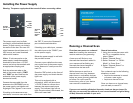
Continue with “Installing the Power Supply” on page 7. If the power
supply is already installed, make sure to run a channel scan after installing
the antenna. See page 8 for more information.
8 in
5 in
Slot
Coaxial cable
running through
pedestal
Coaxial cable
running from
antenna head