


3
2. Determine which programming you will be using. This will determine how you set your switches.
For DISH Network set switches to 119°. For ExpressVu
®
, set switches to 091°.
NOTICE!
This model is PRESET for DIRECTV
®
receivers.
If you have a DISH Network
®
or ExpressVu
®
(Canada) receiver,
you must change the numbered switches inside the dome.
TO CHANGE SWITCHES INSIDE DOME —
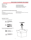
1. Remove screws holding dome to base and remove dome. Place dome in safe spot to avoid damage.
Switches will be set at 101° for DIRECTV
®
. You will be changing these switches.
DIRECTV
®
receivers must be set to the two satellite, oval dish setting. Refer to your receiver manual.
DISH Network receivers must either have the check switch set for SW42 or unknown, no satellite found. See
page 5.
The satellite system has two modes of operation; Tracking Mode and Sleep Mode. When you first turn the
unit on it enters Tracking Mode. In this mode the unit will search and actively follow the satellite as the vehicle
travels. Tracking Mode ends when the unit has successfully finished its search and the vehicle has not moved
for six minutes.
Sleep Mode, this is the unit at rest mode. During Sleep mode the dish will toggle between primary and sec-
ondary satellites as you change channels with the remote. The unit enters Sleep mode about six minutes after
a successful search if stationary, or six minutes after the vehicle stops moving.
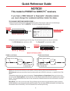
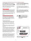
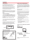
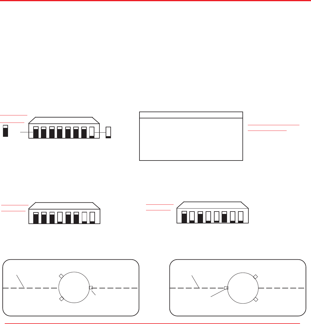
(#1 represents Switch DOWN; #0 represents Switch up)
Sat. Rcvr. Mt. Option Switch Set Position
...................................
1 2 3 4 5 6 7 8
DIRECTV A 0 0 0 0 0 0 0 1
(FACTORY PRESET)
DIRECTV B 1 0 0 0 0 0 0 1
DISH NETWORK A 0 0 0 1 0 0 1 1
DISH NETWORK B 1 0 0 1 0 0 1 1
ExpressVu A 0 1 0 1 1 0 1 1
ExpressVu B 1 1 0 1 1 0 1 1
Models MV-4002, MV-4000, MV-4005
Quick Reference Guide
1 2 3 4 5 6 7 8
1 = DOWN
MOUNTING OPTIONS
SHOWN BELOW
MOUNTING
OPTION A
1 2 3 4 5 6 7 8
1 2 3 4 5 6 7 8
MOUNTING
OPTION A
MOUNTING
OPTION A
0= UP 1= DOWN
0= UP
1= DOWN
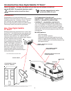
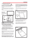
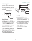
FIGURE 1A, OPTION A
CENTER LINE OF VEHICLE
BASE FOOT
(MUST BE PARALLEL
TO CENTER LINE)
MV-3500
BACK OF VEHICLE
FRONT OF VEHICLE
FIGURE 1B, OPTION B
MOUNT OPTIONS A AND B
CENTER LINE OF VEHICLE
BASE FOOT
(MUST BE PARALLEL
TO CENTER LINE)
MV-4002
BACK OF VEHICLE
FRONT OF VEHICLE
MV-4002
0 0 0 0 0 0 0 1
0 = UP
0 0 0 1 0 0 1 1
0 1 0 1 1 0 1 1