


9
8
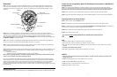
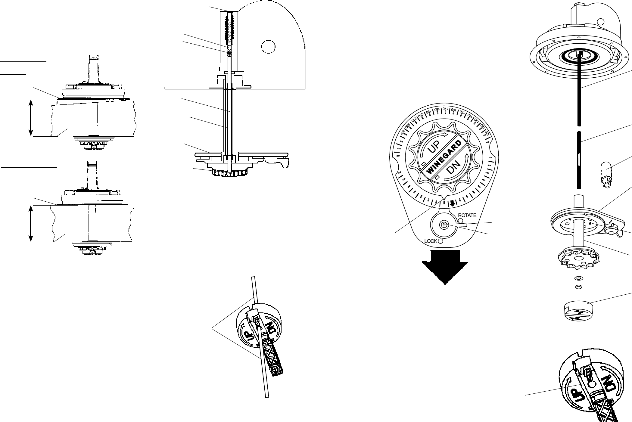
CAUTION!
After initial installation, the antenna SHOULD
ROTATE APPROXIMATELY 360° FROM
TRAVEL POSITION.
The pointer on the directional handle should
point towards the RED SCREW ON THE
ROTATION CLAMP when in the TRAVEL
POSITION.
Figure 15
Figure 16
300
310
320
330
340
350
50
20
30
40
POINT NORTH
290
10
60
70
240
250
Figure 14
POINT TO
BACK OF RV
Pointer must
point to RED
SCREW at
CENTER OF
ROTATION
CLAMP when
in travel
position.
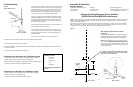
Rotation
Clamp
Red Screw
Elevating Shaft
Threaded Tube
Directional Handle
Extension
Ceiling Plate
(4) #10 Phillips
Flat Head Screws
Directional Handle
Elevating Crank
Handle
(When installed,
extends 2-1/4”
from ceiling.) Snap
Handle into base
when not in use.
ALIGN POINTER
WITH ANTENNA
TRAVEL POSITION
CAUTION!
The antenna must be in the travel position
before aligning the directional handle and
ceiling plate!
TIGHTEN SCREW SNUGLY!
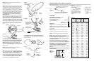
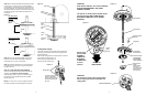
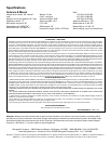
STEP 15. The directional handle and threaded rod will
fit roofs up to 5¼” thick. If you are using wedges to
compensate for roof/ceiling slope, be sure to allow for
this extra thickness. You may add an extension to the
directional handle for thicker roofs. Each extension will
increase the length of the directional handle by 2¼”.
See Figure 11.
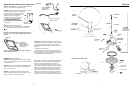
STEP 16. Press the directional handle onto the hub.
Point arrow on the directional handle towards the
rotate/lock lever to orient to the splines.
STEP 17. Install the washer and nut on the threaded
rod. Tighten the nut enough to snug the directional
handle to the hub.
STEP 18. IF YOU ARE USING AN EXTENSION,
adjust the total length of the directional handle and
extension by cutting the directional handle.
After adjusting parts for proper roof thickness, glue
the extension to the directional handle. Use ABS
(plastic pipe) glue.
NOTE: For roofs over 5¼” thick, a longer aluminum
hex shaft is needed. Contact Winegard for this part.
Figure 11
Measure from top of
roof to ceiling.
Figure 12
Cutting Shaft Length
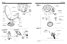
Flip down handle on the elevating crank handle. Slide
elevating crank handle up shaft until snug against the
directional handle.
Mark the elevating shaft at the inside bottom surface of
crank handle housing (Figure 13).
After removing crank handle, cut
shaft at mark. Re-install crank.
Elevating Shaft
Cut elevating shaft at inside
surface of crank handle
housing; shaft goes through
the hex-shaped opening by
the screw.
Figure 13
Plastic Plug
Spacer
Spring
Worm
Gear
Ceiling
Plate
Directional
Handle
Threaded
Rod
WITH ROOF WEDGE
Measure from top of
roof wedge to ceiling.
WITHOUT ROOF WEDGE
TOP OF ROOF
WEDGE
CEILING
TOP OF ROOF
CEILING