


Insert the second (larger) motor connection
into the port underneath “P4 ELEVATION” on
the replacement stationary electronics box.
Insert the first (smaller) motor connection
into the port underneath “P3 AZIMUTH” on
the replacement stationary electronics box.
Align the two holes in the electronics box
and the frame. Insert a screw through each
hole, and tighten with a
1
/
4
” Allen wrench.
Connect the coaxial cable running from the
left side of the LNB to the port underneath
“LNBF.” Make sure the cable still runs behind
the LNB. Tighten until fingertight, and then
tighten a quarter turn with a
7
/
16
” wrench. Do
not overtighten!
Connect the other coaxial cable to the
port underneath “RECEIVER.” Tighten until
fingertight, and then tighten a quarter turn
with a
7
/
16
” wrench. Do not overtighten!
Plug in the power supply connector, and tighten
the two screws on the side of the connector
with a small flat screwdriver.
See “Routing the Cables in Cable Harnesses”
on the next page to finish installing the
electronics box.
Before starting, turn off the power to the unit,
and unplug the unit from the receiver.
Using a #2 Phillips screwdriver, remove the
screws holding the dome to the base.
If applicable, remove the screws connecting
the handle to the unit, and remove the
handle. Set these screws aside; you will need
them later.
Remove the dome.
With both hands on either side of the
reflector, carefully tilt the reflector forward.
With a small flat screwdriver, loosen the
two screws on the side of the power supply
connector, and remove the power supply.
Do not loosen the two screws on the top of
the power supply. Refer to the image on the
bottom of this page.
Loosen and remove the two coaxial cables
underneath “LNBF” and “RECEIVER” with a
7
/
16
” wrench.
Remove all cables from the cable harnesses
marked in the image to the left.
Remove the two screws holding the
electronics box to the frame with a
1
/
4
” Allen
wrench. Gently slide the electronics box
away from the frame.
WARNING
The electronics box is still
tethered to the unit. Do not
pull on the electronics box.
Push down the lock on the first motor
connection. Remove the first motor connection
from the port below “P3 AZIMUTH.”
Push down the lock on the second motor
connection. Remove the second motor
connection from the port below “P4 ELEVATION.”
Remove the electronics box.
Continue with “Installing the Replacement
Stationary Electronics Box” on this page.
1.
2.
3.
4.
5.
6.
7.
8.
9.
10.
11.
12.
1.
2.
3.
4.
5.
6.
7.
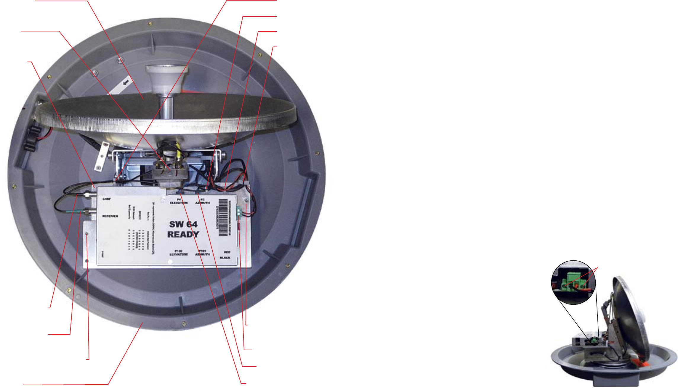
Coaxial cable
underneath “RECEIVER”
Coaxial cable
underneath “LNBF”
Frame
Screw holding electronics
box to the frame
Base
First motor connection
Second motor connection
LNB
Reflector
Cable harness 1
Cable harness 2
Cable harness 3
Cable harness 4
Power supply connector
Screw holding electronics
box to the frame
Two screws to remove from power supply
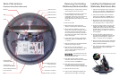
Removing the Existing
Stationary Electronics Box
Parts of the Antenna Installing the Replacement
Stationary Electronics Box
Overhead View (Dome Removed)