


Page 2 Model 490-95
© 2004 Xantech Corporation
INSTALLATION
These units, equipped with a 7-foot cable and 3.5 mm stereo mini plug, are intended to be plugged directly into the "IR
RCVR" or "AUX" jack on Xantech Connecting Blocks, such as the CB12(included), CB60, 789-44, 791-44, etc. The 490-
95 should be used in installations where the connecting block is within reach of the 7-foot cable -- such as when installing
the 490-95 in a cabinet where the controlled equipment is behind closed doors.
PLACEMENT
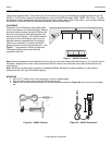
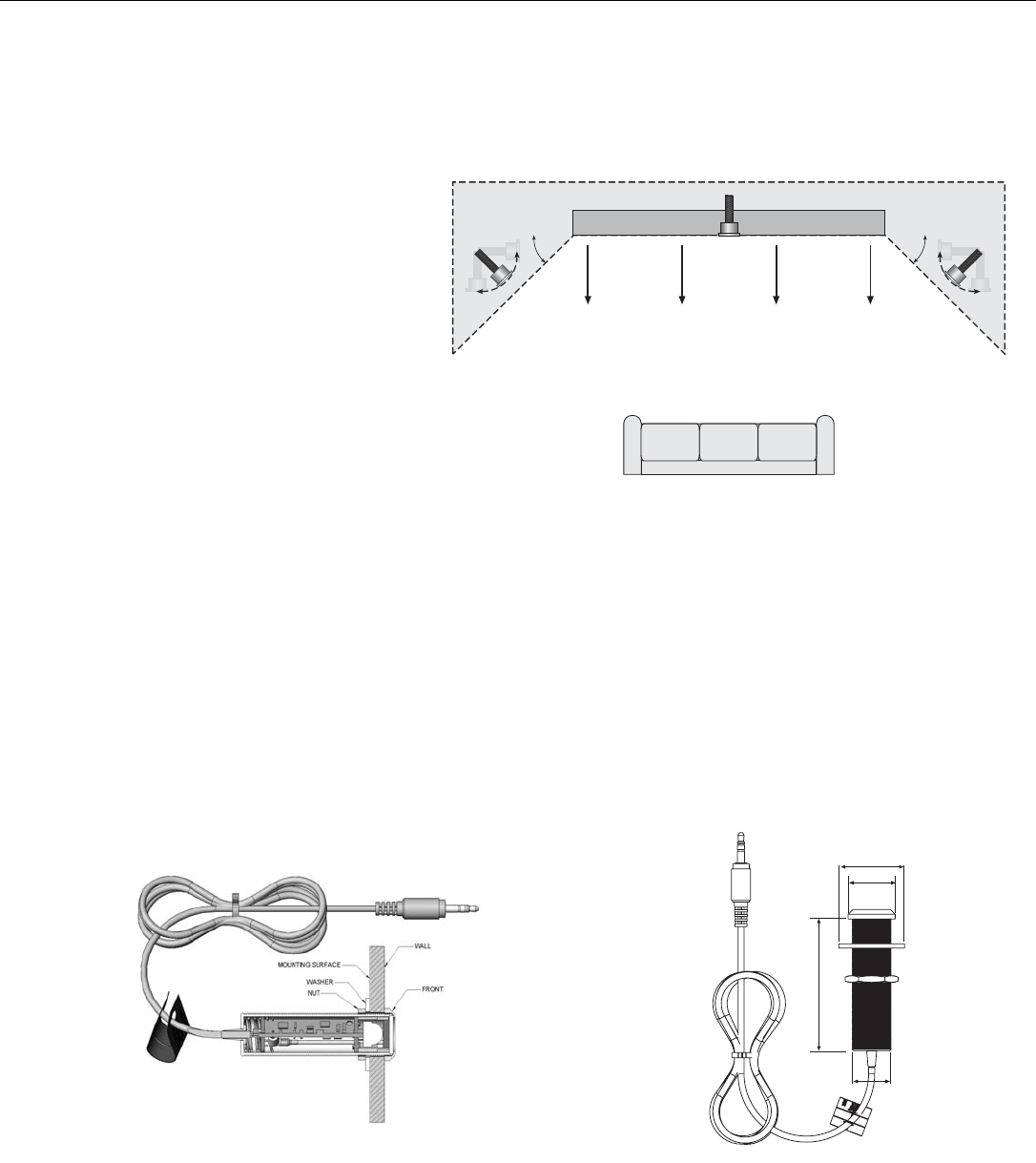
Placement of the IR Receiver does matter when
used in the presence of a Plasma Display. Ideally it
should be placed at areas around the Display with
the front of the receiver flush with the front of (or
set back from) the Display. If the 490-95 needs to
be placed in front of the display (such as on an
adjacent side wall perpendicular to the display),
make sure it is placed at a location at least 45
degrees off axis from the corners of the unit – see
Figure 1. The presence of Direct Sunlight and
Fluorescent Lighting should not effect the
reception of this unit.
Note: Plasma interference can be reflected off of any item it comes into contact with within approx. 3 ft. from the front of
the display. Keeping this in mind, make sure that the 490-95 is free of any obstruction that might reflect back into the
receiving eye.
Note: While this unit shows strong rejection to standard 50/60Hz ‘ballasted’ fluorescent lighting, it is still prone to
interference from CFL style Fluorescent lighting.
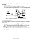
MOUNTING
1. Drill a 0.75” (19mm) hole in any flat surface, such as a cabinet panel.
2. Pass the lead and the body of the 490-95 through the hole.
3. Secure from the rear with the Washer and Nut (all supplied) as shown in Figure 2a. Be sure not to over-tighten
nut.
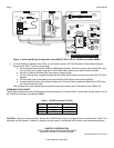
1.25
0.90
2.75
0.75
Figure 2a – 490-95 Features Figure 2b – 490-95 Dimensions
45°
45°
PLASMA DISPLAY
Figure 1 – 490-95 Placement