


Model 490-95 Page 3
© 2004 Xantech Corporation
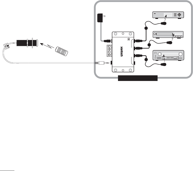
APPLICATION WIRING
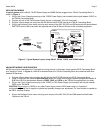
A typical system, with a 490-95, 781RG Power Supply and 283M Emitter plugged into a 789-44 Connecting Block, is
shown in Figure 3:
1. Plug in the 2.1mm Coaxial power plug of the 781RG Power Supply (not included) into the jack labeled 12VDC on
the 789-44 Connecting Block.
2. Plug the AC end of the 781RG power Supply into an ‘un-switched’ 120v AC Line outlet.
3. Plug the 3.5mm stereo mini plug from the 490-95 into the IR RCVR input on the 789-44 Connecting Block
4. Plug in the Emitters 3.5mm mono mini plug such as any of the 282, 284, 283 and 286 series into the jacks labeled
EMITTERS on the 789-44 and affix the opposite end to the IR Sensor Window of the controlled equipment.
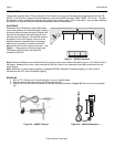
283M
Blink-IR
Mouse Emitter
To 120 V AC
(unswitched)
781RG
Power Supply
789-44
Connecting Block
283M
Emitter
283M
Emitter
Equipment Rack
Hand Held
Remote
VCR
490-95
Micro Link
Plasma-Friendly
IR Receiver
12VDC
+12 VDC
GND
STATUS
IR IN
EMITTERS
IR
RCVR
789-44
CONNECTING BLOCK
®
Satellite Receiver
AV
Receiver
Figure 3 - Typical System Layout using 490-95, 789-44, 781RG, and 283M Emitters
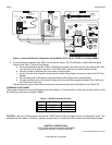
ADVANCED WIRING CONFIGURATION
490-95 may also be used where the 7-foot lead is not long enough. In this case, simply use the CB12 Connecting Block
as a “break-out” block. In Figure 4, a 490-95 is extended down to a 789-44 Connecting Block and combined with other
Xantech IR Receivers.
1. Plug the 3.5mm stereo mini plug from the 490-95 into the IR RCVR input on the CB12 Connecting Block.
2. Using 3-Conductor wire (refer to Specifications section for proper Wire Gauge) connect the terminals labeled V
G S of the CB12 to the terminals labeled +12VDC, GND, and IR IN on the 789-44 Connecting Block (or other)
3. Plug in the 2.1mm Coaxial power plug of the 781RG (or 782) Power Supply (not included) into the jack labeled
PWR on the 789-44CB.
CAUTION! Do not
plug in a 781RG or any other Power Supply into the CB12 when using in a “break-out”
configuration. This will put 2 supplies in parallel and possibly damage your equipment. If a ‘local’ emitter is needed on
the CB12, see Step 5 below.
4. Plug in the Emitters 3.5mm mono mini plug such as any of the 282, 284, 283 and 286 series into the Emitter
Outputs on the 789-44.