


3
Remote Control Switchers
CC62
The CC62 should normally be plugged into an unswitched AC outlet. However, if the power to the CC62
is interrupted by a power failure or other reason, the internal memory will retain the last selected switched
condition for each of the relays.
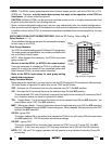
IR RCVR INPUT CONNECTOR
This 4-terminal input has electrical connections for +12V, GND
(chassis ground), GND (IR signal ground) and IR IN (IR signal).
The GND terminal closest to the IR IN terminal is provided so that,
if needed, the IR signal ground can be isolated from the chassis
ground. This isolation may be necessary in some instances to
prevent ground loop problems, etc.
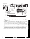
A special jumper, inside the CC62, gives you the option to make
the grounds common or have them isolated. Refer to Fig. 3.
To gain access to this jumper, remove the eight screws that
secure the top cover to the metal chassis. Carefully lift the cover
off. When you have made the adjustment, reassemble in reverse
order.
NOTE: When shipped from the factory, the jumper is installed in
the ON (common) position.
CAUTION: When powering IR receivers and keypads directly from the CC62, you
must leave the jumper
installed in the ON position
so that the two G terminals are connected in common. This provides the
needed ground return for the IR signal.
Change the jumper to the OFF position only when powering IR source devices separately from the
CC62 and there is a need for electrical isolation
.
INSTALLATION
Typical applications for the CC62 are as follows:
• To activate shade or drape pulls, projector lifts, screen drops, etc. Use Momentary On modes at
relay #1 to close and at relay # 2 to open, if such devices require two separate dry contacts to operate.
• To switch low voltage lighting or other devices: Use Toggle or the ON & OFF (pair) commands. Pair
commands allow a known ON/OFF status from remote rooms where visual status is not possible.
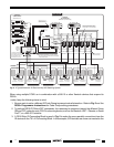
• Amplifier A/B switching: Each relay can be connected so that a stereo pair of speakers (in each remote
room) can be switched between two AV receivers. This effectively creates a simple 2-zone system
addressable from each room. Refer to Fig. 4.
Each remote control and keypad used in the system needs to be programmed with Toggle or Pair
commands from the RC68+ to do the A/B switching. In addition, each room needs a dedicated learning
remote or keypad having the RC68+ IR commands that operate the specific CC62 relay for each room.
NOTE: The CC62 is shown connected to Xantech 760-00 Match Maker room volume controls (Fig. 4)
for individual room control. When set correctly, the Match Makers will provide the proper impedance match
between the speakers and the amplifiers. See the 760-00 Installation Instructions for details.
• Another important application of the CC62 is to provide IR-to-switch closures for a 590 Programmable
Controller. This permits multiple sequenced commands to be generated from a single RC68+ IR
command or to convert RC68+ commands to other brand commands. Fig. 5 illustrates such a system.
Up to 16 independent closures are possible by using as many as three CC62's with a 590-00.
Use Momentary On programming.
Jumper ON Position.
(Common ground
between GND and GND
terminals - factory
default setting)
Metal Chassis
Jumper OFF Position (Isolated Grounds).
No connection between the GND and GND terminals.
PCB
PCB
JP1
LED1
JP1
LED1
Fig. 3 Location and Adjustment of
Grounding Jumper