


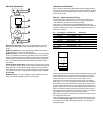
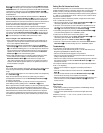
Rear Panel Connections
¡ Cover Plate Screwholes – After you have completed installation, these screw-
holes accept the screws supplied with your Decora-style cover plate to attach it to
the KP 1.
™ Mounting Screw Slots – Use the supplied machine screws to attach the KP 1 to
an electrical junction box or plaster ring using these slots.
£ RJ-45 Connector – Insert one end of the RJ-45 connector for the cable connecting
the KP 1 to the PA 4000 into this left-facing jack. When the other end of the cable is
plugged into the appropriate jack on the PA 4000, the cable carries control signals gen-
erated by the KP 1 and the signals received by the optional IR sensor to the PA 4000,
and a +12 Volt power supply from the PA 4000 that powers the optional IR sensor,
when installed.
¢ 3-Pin IR Sensor Terminal Block – When installing an optional IR sensor, connect
it to the appropriate terminals. Connect the sensor’s three conductors to the Ground, IR
Signal Output and +12V DC terminals by slightly unscrewing each of the set screws
shown, inserting the bare wire end into the downward-facing hole under the set screw,
then tightening the set screw. The terminal block is internally connected to the RJ-45
Connector £.
∞
IR Sensor Cutout – If you will be
installing an optional IR sensor, punch out this
cutout. See the detailed installation instructions in the next section.
¡
™
∞
¢
£
™
¡
KP 1
G
IR
12V
Installation and Connection
The KP 1 should only be installed by qualified personnel. Before installing this device,
make sure you are aware of all local building codes and NEC standards that may apply
to installing electrical wiring inside the walls of your home. If you have any questions,
consult a custom installer.
Step One – Prepare and Install the Wiring
You will need to prepare an appropriate length of CM- or CP-rated Category 3 or
Category 5 UTP, 8-pin, 8-conductor wiring. For runs over 250 feet, thicker CL2/CL3,
4-pair, 22AWG wire may be required to preserve signal integrity.
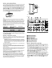
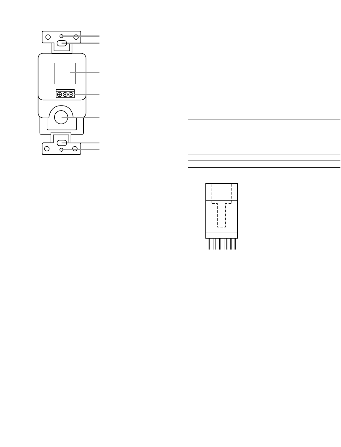
Connect the KP 1 to the PA 4000 using standard T568B Straight Through wiring.
Looking at the connector with its clip down and the wires coming out of the connector
toward you, numbered from left to right, the typical pin assignments are as shown in
Wiring Chart 1 and Figure 1.
Pin # KP 1 Pin Assignment Striped Wire Colors Solid Wire Colors
1 On/Off White with Orange Stripe White
2 Volume Down Orange with White Stripe Brown
3 Volume Up White with Green Stripe Yellow
4 Key Sense Blue with White Stripe Green
5 Ground (GND) White with Blue Stripe Red
6 IR GND Green with White Stripe Black
7 IR Signal White with Brown Stripe Orange
8 +12 Volts Brown with White Stripe Blue
Wiring Chart 1
Either the striped or solid color standards may be used, depending on the type of cable
being installed. Make certain that the same color wire is connected to the same pin
number at each end of the wire. Make sure that the twisted pairs of wires consist of
those attached to pins 1 and 2, pins 3 and 6, pins 4 and 5, and pins 7 and 8.
When attaching the connectors to each end of the cable, strip the outer insulation
jacket about 1-1/2" to 2" from the end. The cable is constructed of four twisted pairs
of wires. Flatten the wire ends to prepare them for insertion into the connector.Then
trim the wire ends to approximately 1/2" in order to leave as little untwisted wire as
possible. Fully insert the wire into the connector. Carefully crimp the connector in accor-
dance with the connector manufacturer’s instructions, making sure that each wire is
securely fastened in the connector and that no insulation is caught in the connector. If
using stranded conductors, make sure that there are no loose strands.
Before making any connections to the PA 4000, be certain that it has been turned off
and unplugged from the AC outlet.
Home-run the cable from the KP 1 to the PA 4000. Insert the RJ-45 connector on the
cable into the RJ-45 Connector £ on the back of the KP 1 until it clicks into place.
The connection to the PA 4000 and appropriate configuration of the PA 4000 are
described in Step Four.
12345678
Figure 1