


Step Two – Install an Optional IR Sensor
If you are installing the optional IR sensor, you also need to prepare the sensor’s ribbon
cable. The recommended Xantech 490-00 Micro Link comes with a 7-foot long, 3-con-
ductor ribbon cable. Trim the ribbon cable to 3 or 4 inches. Strip the wire ends 1 to
1-1/2 inches, then fold each bare end over itself twice and twist it.This creates a slightly
thicker wire to connect to the KP 1‘s IR Sensor Terminal Block 4. Break out the
IR Sensor Cutout 5 on the front of the KP 1 by gently pressing out, and insert the
Micro Link sensor through the hole from the front, cable end first. Install the sensor’s
nut on the threaded body of the sensor before connecting the ribbon cable to the
KP 1’s terminal block. Tighten the nut to secure the sensor in its cutout.
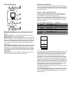
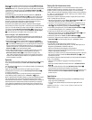
Carefully connect the bare ends of the sensor’s three wires to the KP 1
Terminal
Block ¢ as shown in Figure 2 and Wiring Chart 2. Loosen the set screw for each ter-
minal position, insert the end of the bare wire into the hole directly under the corre-
sponding set screw, and tighten the set screw, making sure that no wires touch each
other or other terminals. If a different compatible IR sensor is used, match the wire
color used to the specific circuit function. Then connect the wires to the KP 1 Terminal
Block ¢ in accordance with Wiring Chart 2.
Position on KP 1 Position on Micro Link Circuit Function
Terminal Block Ribbon Cable
Right Middle +12 Volts
Middle Red or White Stripe on IR Signal (Output
Outside of Ribbon of Micro Link)
Left Opposite to Stripe Ground
Wiring Chart 2
No other connections are required, as the terminal block is internally connected to the
KP 1’s RJ-45 Connector £ for connections to the PA 4000 and onward to other IR-
controlled devices as applicable.
Step Three – Install the KP 1 In the Wall
Although the KP 1 is designed to fit into a standard single-gang electrical junction box
or plaster ring, always check the fit before cutting into a wall. Follow these guidelines
for optimal placement of the KP 1:
CAUTION: THE ELECTRICAL JUNCTION BOX IN WHICH THE KP 1 IS MOUNTED
MUST BE DEDICATED TO LOW-VOLTAGE CONTROL SYSTEM APPLICATIONS. MAKE
SURE THAT NO AUDIO/VIDEO OR AC MAINS WIRING PASSES THROUGH OR TER-
MINATES IN THIS BOX!
If you install the optional IR sensor, avoid placing the KP 1 in an area subject to poten-
tial interference with the IR signal.
Locate the KP 1 at least 4 inches from a dimmer switch, or install it inside a metal box
rather than plastic, as the dimmer switch may generate electronic noise that might
interfere with the KP 1.
The KP 1 may be installed in a multi-gang junction box with other low-voltage controls.
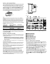
Please refer to Figure 3 for guidance in installing the KP 1 into a junction box and
attaching a Decora-style cover plate.
Gently place the KP 1 in the junction box or plaster ring and attach it by inserting the
supplied mounting screws through the
Mounting Screw Slots ™ of the KP 1
until it is aligned correctly and tighten the screws.
Attach a Decora-style cover plate (not included) by placing the screws provided
with the cover plate through the plate’s holes and into the KP 1’s Cover Plate
Screwholes ¡. Hand-tighten the screws so that the cover plate is secure, taking care
so as not to overtighten and break the cover plate. Although any color or compatible
style of wall plate may be used with the KP 1, the KP 1 itself should not be painted,
in order not to cover the printed button labels.
490-00
IR Receiver
Red (or White)
Stripe
OUT
+12V
GND
7’ Ribbon Cable
Copyright 2000 Xantech Corporation
a IR Remote Control Output
b MR On/Off Command Switch
c Remote IR Sensor Inputs
d Remote Keypad Inputs
e Bridge 1 Amplifier Mode Switch
f Bridge 2 Amplifier Mode Switch
g Power Control Mode Switches
h Volume/Output Level Controls
Step Four – Connect the KP 1 to the PA 4000
•When the PA 4000 is used in the Normal mode, feeding four pairs of speakers, con-
nect the cable from each KP 1 to the Remote Keypad Input d corresponding to
the proper speaker channel for that room.
•When the PA 4000 is used in one of the Bridged modes, connect the cable from the
KP 1 to the Remote Keypad Input d corresponding to the lower numbered jack
for the pair of channels being bridged. Thus, when Output Channels 1 and 2 are
bridged, connect the KP 1 cable to the Remote Keypad Input d connector for
Channel 1. When Channels 3 and 4 are bridged, connect the KP 1 cable to the
Remote Keypad Input d connector for Channel 3.
•The proper Remote Keypad Input d connections are determined by whether
the amplifier channels are used in their Normal mode or if they are bridged. Use of a
separate input source for Channel 3 does not impact the keypad connections.
• When a KP 1 is connected to any Remote Keypad Input d, the Power Control
Mode Switch g for that channel must be placed in the far right position, under
the words “ON/KEYPAD” to enable the KP 1’s Power Button 3 to turn on the
PA 4000.
AC/DC
TRIG.
BRIDGE 2
BRIDGE 2
DN
CH4 CH3 CH2 CH1
CH3
CH1
KEYPAD
INVOLUME
REMOTE
CONTROL OUT
MR ON/OFF
COMMAND
AMP
MODE
ON/
KEYPAD
MUSIC
SENSE
AC/DC
TRIG.
ON/
KEYPAD
MUSIC
SENSE
AC/DC
TRIG.
ON/
KEYPAD
MUSIC
SENSE
AC/DC
TRIG.
ON/
KEYPAD
MUSIC
SENSE
ON
OFF
NORMAL
CH3/4
NORMAL
CH1/2
OFF
UP DN UP DN UP DN UP
CH4
BRIDGE 1
CH2
BRIDGE 1
CH3
SEPARATE
ON
CH4 CH1
REMOTE IR SENSOR
IN
CH3 CH2
CH 3 IN MAIN
3-30V
AC/DC
TRIGGER
INPUT
CH4 CH3 CH2 CH1
BRIDGE 2 BRIDGE 1
CH4 BRIDGE 2 CH3 CH2 BRIDGE 1 / CH1
POWER
CONTROL
MODE
a
b
c
d
efgh
Front
Panel
Decorator
Cover
Plate &
2 Screws
(not included)
1/8" x 3/4" Machine
Screws (2) (included)
Wallboard
J-Box
RJ-45
Connector
(cable
not shown)
Figure 2
Figure 3
Rear of PA 4000