


Xantrex AC to DC Converter
16 975-0301-01-01
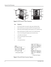
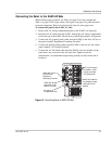
4. AC breaker positions 1 and 2 have been removed from the removable
faceplate on the panel. Remove extra positions from the panel by twisting the
knockouts back and forth. Any knockouts that have been accidentally
removed can be replaced with one of the following parts: ITE Gould QF-3 or
Cutler Hammer/Bryant/Westinghouse FB-1B.
5. If you intend to mount the XADC and panel remotely, install a UL/CSA
approved strain relief on both of the bottom AC and DC wiring compartment
holes.
6. If you intend to mount the XADC and panel remotely, you may need to
increase the length and gauge of the DC cables from the panel to the XADC
(see “Configurations” on page 15).
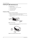
To prepare the XADC for remote installation:
Make the following changes to the XADC if you intend to mount the XADC and
panel remotely.
1. Remove the plastic wire protection grommets from the AC and DC wiring
compartment holes.
2. Install a UL/CSA approved strain relief on both the AC and DC wiring
compartment holes.
3. You may need to increase the length of the AC cables from the XADC to the
panel (use a minimum of 14 AWG wire for any such extensions).
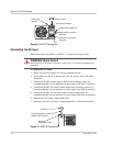
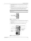
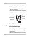
To prepare the XADC for connected installation:
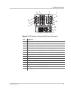
See Figure 11 for additional information.
Make the following changes to the XADC if you intend to connect the XADC and
panel and mount them in a single mounting hole (12 in. × 12 1/8 in. – 30.5 cm ×
30.7 cm).
1. Remove the four screws from the XADC faceplate and remove the faceplate.
2. Remove the two side mounting flanges and keep them for re-use.
3. Take one of the mounting flanges from the mounting hardware bag in the
panel shipping box (see Figure 11) and screw it to the top of the XADC.
The mounting flange screw holes will line up with the corresponding pilot
holes in the XADC.