Instruction Manual
748332-F
April 2003
2-2 Installation Rosemount Analytical Inc. A Division of Emerson Process Management
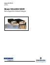
Model NGA2000 NDIR
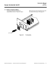
2-3 LOCATION
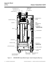
Install the NDIR Analyzer Module in a clean,
non-hazardous, weather protected, vibration
free location free from extreme temperature
variations. For best results, install the
instrument near the sample stream to minimize
sample transport time. Operating ambient
temperature is 0
o
C to 45
o
C (32
o
F to 113
o
F).
Sample dewpoint is 40°C or less.
NOTE
Unrestricted air flow in the rear of the Ana-
lyzer Module is critical to its performance
and reliability..
2-4 GAS SPECIFICATIONS
a. Calibration Gases
All applications require a zero standard gas
to set the zero point on the display and
external data acquisition devices. if the
factory provided Calibration and Data Sheet
(in the rear of the manual) specifies a
background gas, use this as a zero gas. If
a background gas is not specified, use dry
nitrogen.
Span gas should be between 75% and
100% of fullscale span. Flowing reference
(if used) should be dry nitrogen.
b. Flow Rate
Recommended sample flow rate is 1 to 2
SCFH (500 TO 1000 cc/min). A lower flow
rate will not affect readings but may result in
an undesirable time lag. Excessive flow
can produce increases cell pressurization
and reading error.
At higher cell pressures, the nonlinearity of
the calibration curve increases. Therefore,
the calibration curve should be redrawn for
higher flow rates. Also, the effect of
increased cell pressurization can be
negated if the same flow rate is used for
sample, zero and span gases. But, if flow is
high enough to cause elevated pressure,
careful control (tighter tolerance) of flow rate
is required to avoid errors.
If flow is kept at or below 2 SCFH (1 L/min),
sample and instrument temperatures reach
equilibrium regardless of stream
temperature (within specifications; 0 to
55°C). At extremely high flow rates, this
may not be true, although no such effect
has been noted up to 18 SCFH (9 L/min).
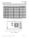
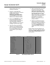
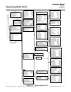
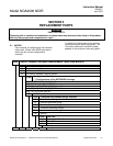
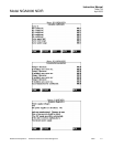
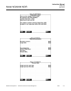
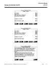
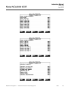
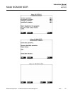
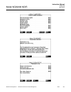
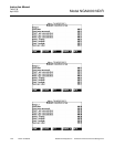
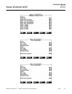
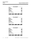
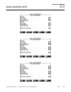
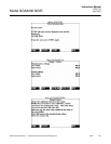
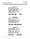
See Table 2-1 on page 2-3 for cell purging
times at atmospheric sample pressure.
c. Sample Pressure/Filtration
Sample should be introduced to the
Analyzer Module at a maximum 690 hPa-
gauge (10 psig). Pressurized applications
are available, which require pressurized
cells and careful control of flow rates,
consult factory for these applications.
Sample should be filtered for particulates
down to two microns.
d. Leak Test
The Analyzer Module is completely tested
at the factory for gas leakage. The user is
responsible for testing for leakage only at
the inlet and outlet fittings on the rear panel.
The user is also responsible for internal leak
testing periodically and if any internal
pneumatic components are adjusted or
replaced (with a test procedure chosen by
the user).
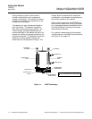
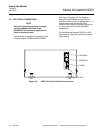
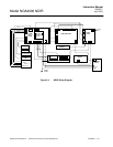
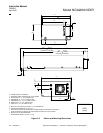
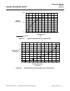
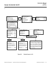
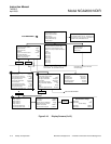
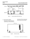
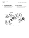
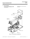
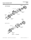
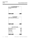
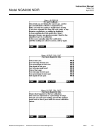
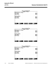
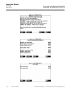
2-5 GAS CONNECTIONS
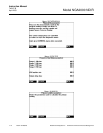
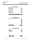
(See Figure 2-2 on page 2-3) Connect inlet
and outlet lines for sample/zero/span and
flowing reference (if applicable) to
appropriately labeled fittings on the rear
panel. All four connections are 1/4 inch
ferrule-type compression fittings.