Installation
312787G 5
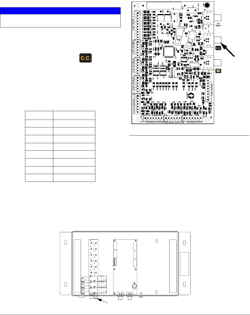
Connect Module to Fluid Station Board
1. Remove the Fluid Station cover.
2. See F
IG. 1. Connect a 5-pin electrical cable (EC)
from the labeled connection port
(J11) on the
fluid station control board to the color change board.
Also see F
IG. 2 and FIG. 5.
NOTE: See Table 1 for a list of available cables to con-
nect the color change control module and fluid station.
Recommended length is 3 ft (1.0 m) or 6 ft (2.0 m).
To Install a Second Control Module
If you are using two color change modules to add colors,
connect a 5-pin electrical cable from the first color
change board to the second color change board. See
F
IG. 5.
Connect Air Supply to Control Module
Connect a 1/4 in. (6 mm) OD tube (13) between the sys-
tem’s air manifold (at the bottom rear of the fluid station)
and the module air inlet fitting (29). See F
IG. 3.
The air supply must be clean and dry. Use a 5 micron fil-
ter. Regulate the air pressure to 75-100 psi (0.52-0.70
MPa, 5.25-7.0 bar).
NOTICE
To avoid damaging circuit board when servicing, wear
grounding strap on wrist and ground appropriately.
Table 1: Intrinsically Safe CAN Cables
Part No. Length in ft (m)
15U531 2 (0.6)
15U532 3 (1.0)
15V205 6 (2.0)
15V206 10 (3.0)
15V207 15 (5.0)
15V208 25 (8.0)
15U533 50 (16.0)
15V213 100 (32.0)
FIG. 2: Fluid Station Control Board Connection
J11
(Color
Change
Module)
F
IG. 3: Solenoid Air Connection
TI12824a
29


