6
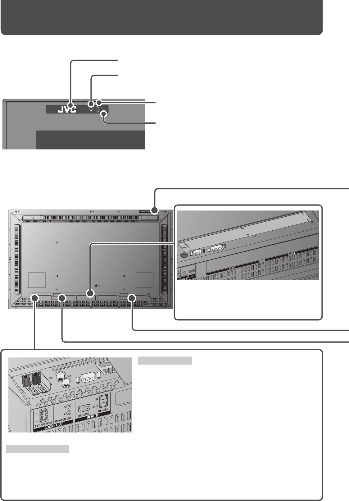
Front panel
Rear panel
Remote sensor:
Point the front end of the remote control toward here.
Eco sensor:
Detects brightness of the room (see page 23).
Self-diagnostic lamps:
These lamps light/fl ash if something abnormal occurs with
the monitor (see page 36).
Power lamp:
When the monitor is turned off : Unlit.
When the monitor is turned on: Lights in green.
When the monitor is in sleep mode: Flashes in orange.
When the monitor is in standby mode: Lights in orange.
Input card slots (SLOT-1, SLOT-2):
Optional input cards can be installed in these slots.
• For details about input cards, refer to the
instructions of the input card.
REMOTE terminals
Connect external control equipment (see pages 12, 31 to 33).
RS-232C terminal: Connect to the RS-232C terminal of a
personal computer. For the control method
using this terminal, consult an authorized JVC
dealer.
RS-485 terminals:
IN terminal: Connect external control equipment.
OUT terminal: Connect another component to send out the
control signal coming into the IN terminal
(cascade connection).
AUDIO OUT terminals
Connect external speakers or audio equipment.
EXT. SPEAKER terminal: Connect external speakers (commercially available) (see page 10).
• To use this terminal, set “SPEAKER SELECT” on the main menu to “EXT. (external)” (see page 21).
MONITOR OUT terminals: Connect to the audio input terminals of audio equipment such as an amplifi er (see
page 12).
Parts Identifi cation
05-39_GM-H40L1G-f.indd 605-39_GM-H40L1G-f.indd 6 05.10.6 1:13:18 PM05.10.6 1:13:18 PM


