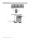
Rockwell Automation Publication 1734-UM001E-EN-P - July 2013
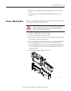
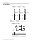
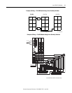
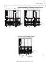
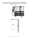
Install POINTBlock I/O Modules 79
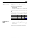
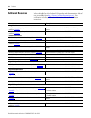
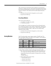
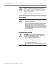
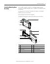
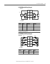
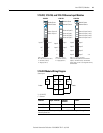
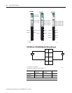
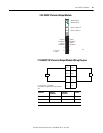
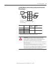
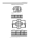
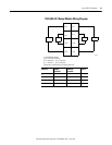
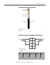
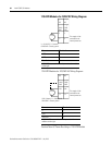
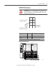
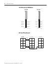
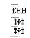
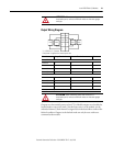
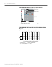
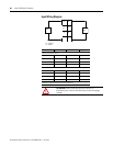
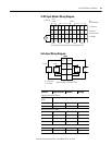
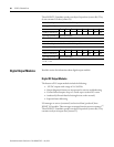
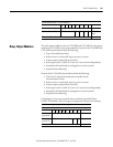
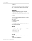
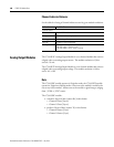
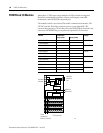
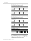
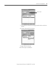
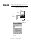
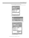
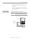
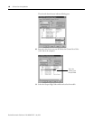
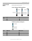
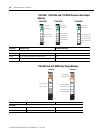
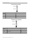
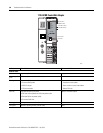
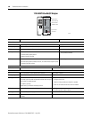
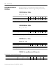
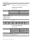
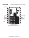
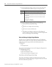
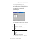
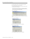
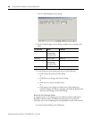
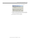
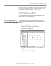
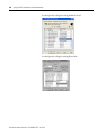
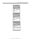
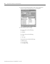
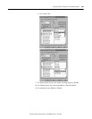
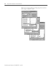
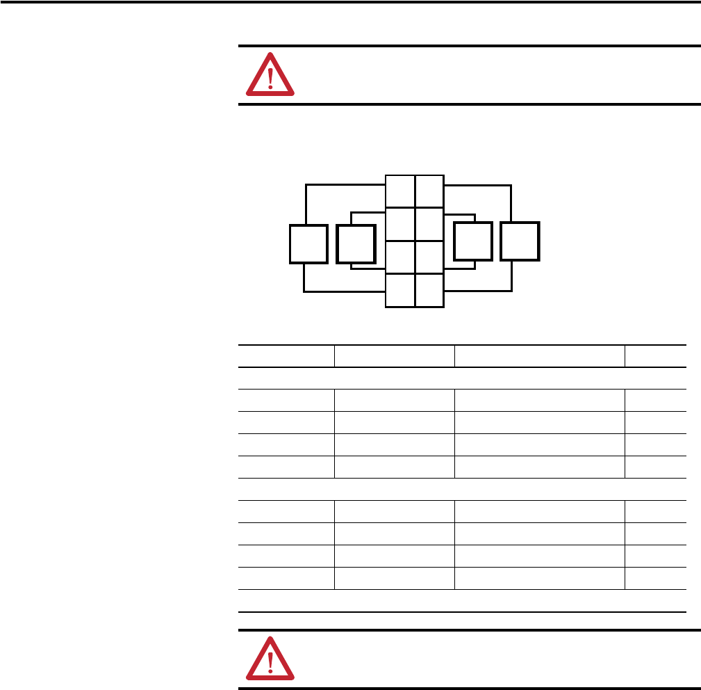
Output Wiring Diagram
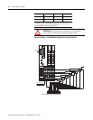
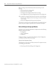
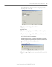
Outputs are electronically protected to 0.75 A. Module outputs are selectable for
latched mode or auto-reset mode. (Latched/auto reset is set by module, not by
individual channel.) Each channel is assigned a bit in the data table to indicate the
faulted condition. Outputs in the latched mode can only be reset with a user
command to the module.
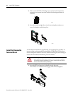
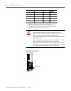
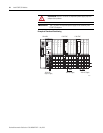
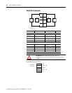
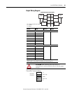
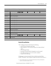
ATTENTION: When connecting more than one wire in a
termination point, make sure that both wires are the same gauge
and type.
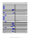
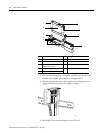
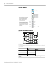
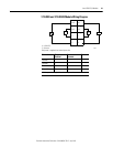
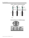
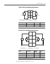
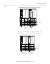
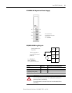
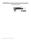
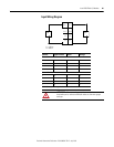
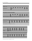
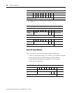
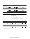
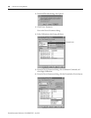
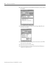
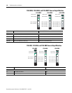
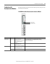
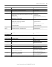
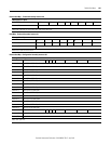
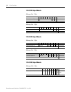
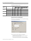
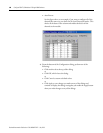
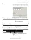
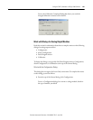
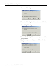
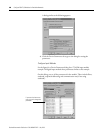
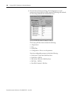
Channel Output Terminal Common Terminal Power
Remote Termination Block 3
Channel 0 0 6
Channel 1 1 7
Channel 2 2 4
Channel 3 3 5
Remote Termination Block 4
Channel 4 0 6
Channel 5 1 7
Channel 6 2 4
Channel 7 3 5
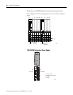
Module power is supplied from the internal power bus.
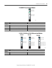
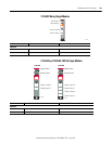
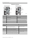
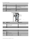
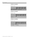
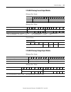
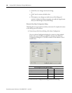
ATTENTION: When connecting more than one wire in a
termination point, make sure that both wires are the same gauge
and type.
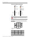
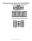
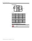
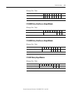
Out 0
Out 1
Out 3Out 2
CC
CC
Load Load
Load
Load
V = 12/24V dc, C = Common
Field power is supplied from internal power bus
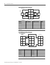
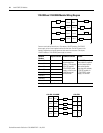
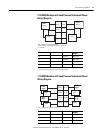
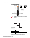
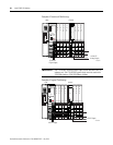
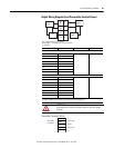
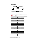
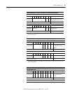
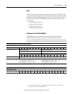
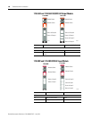
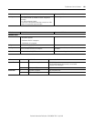
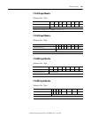
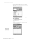
0
2
6
3
1
7
45