Controls and Functions
6 Q-650i Series Installation/Operation Manual
PRE
L
IMINAR
Y
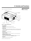
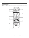
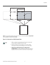
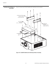
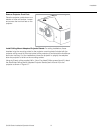
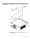
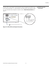
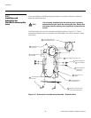
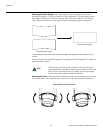
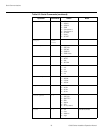
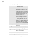
• FRONT IR SENSOR
Receives infrared signals from the remote control unit.
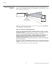
• EXHAUST VENT
Warm air exits the projector through this vent. Ensure that it is not blocked.
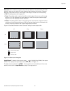
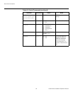
• STATUS LED
Indicates projector status as follows:
• Solid green = AC power present, ready to turn on.
• Flashing green = Projector is initializing; keypad functions not allowed.
• Off = Normal operation.
• Flashing red = Over temperature, user intervention (clear vents, turn on AC) may fix
problem
• Solid red = Error that requires servicing (fan failure, Power-on Self-Test (POST)
failure).
2.2
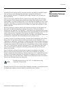
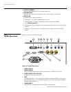
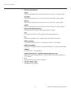
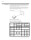
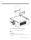
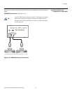
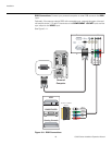
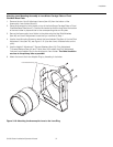
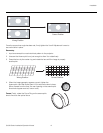
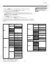
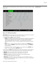
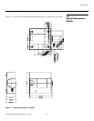
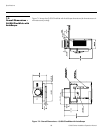
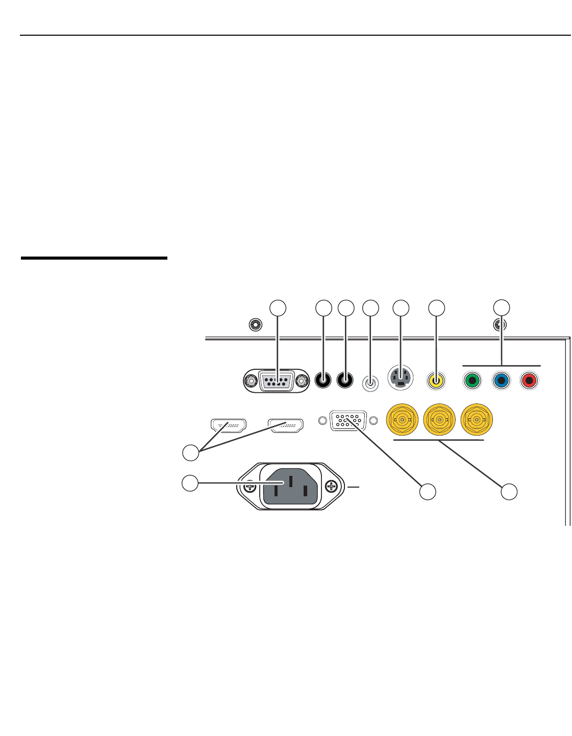
Q-650i Rear Panel
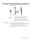
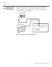
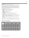
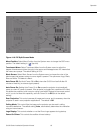
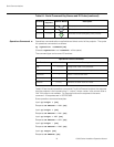
Figure 2-2 shows the Q-650i rear panel.
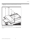
Figure 2-2. Q-650i Rear Panel
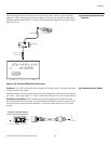
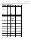
1. HDMI 1 (Digital)
HDMI 2 (Digital)
HDCP-compliant digital video inputs for connecting an HDMI or DVI source.
2. POWER INPUT (100 to 240 VAC)
Connect the Q-650i to power here.
3. RGB
Provides a standard, 15-pin VGA-style connection to either an RGB or component
high-definition source, or to a personal computer. The Q-650i automatically detects
the input signal resolution.
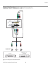
4. COMPONENT 2
Three BNCs for connecting component (YPbPr) video sources.
AC
AC
1
5
2
3
6
78911
4
10