


A-8
B
R
I
D
G
I
N
G
A
N
D
R
O
U
T
I
N
G
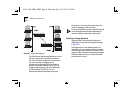
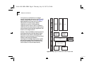
It is important to understand that in a bridged
network the addressing structure for both IP and IPX
relates to a single network. If the units in
Figure A-3
were bridges and not routers, then an IP node on
LAN A could, for example, have an address
140.56.10.0, the node on LAN B an address
140.56.10.2, and the node on LAN C, an address of
140.56.10.3. All the nodes, therefore, are able to share
the same Class B network address, regardless of their
location on the bridged network.
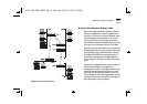
However, if there were NetWare nodes throughout the
three bridged sites, they would also share the same
IPX network number. If each of the bridged LANs
supported a network server, each with its own unique
network number, and an IPX address is
misconfigured, the NetWare network server consoles
will report the message ‘Router Configuration Error –
Router XXXXX claims that LAN is XX-XX-XX-XX’. (The
router it refers to is in fact the network server).
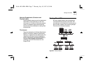
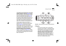
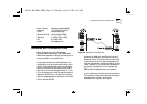
Figure A-4
Open Systems Interconnection Network Layer Model
Others
Ethernet
Hardware
Link Level Control
ARP
RARP
Internet Protocol (IP) and
Internet Control Message Protocol
(ICMP)
Transmission
Control
Protocol
(TCP)
Telnet
File
Transfer
Protocol
(FTP)
Network
File Store
(NFS)
User
Database
Protocol
(UDP)
PHYSICAL
DATA LINK
TRANSPORT
SESSION
PRESENTATION
APPLICATION
NETWORK
Rc.bk : RCAPPA.FRM Page 8 Thursday, July 10, 1997 9:53 AM