


6
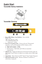
Transmitter Operations
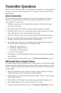
There are three different methods of applying the transmitter’s locating signal to
the target conductor: Direct Connection, 3M
™
Dynatel
™
Dyna-Coupler Clamp,
and Induction.
Direct Connection
This is the preferred mode of operation because the transmitter is connected
directly to a metallic portion of the target conductor (hydrant, meter, riser,
valve, sheath, or tracer wire).
1. While the transmitter is off, plug the direct connect cable into the output
jack of the transmitter.
2. Attach the red lead of the direct connect cable to the target conductor.
3. Extend the black lead as far as possible from the target conductor at a right
angle (90 degrees) to the suspected path of the target.
4. Insert the external ground rod and attach the black lead of the transmitter.
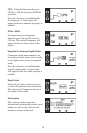
5. Turn the transmitter ON by pressing the frequency button. Select 8 kHz,
82 kHz, or both (8 K and 82 K will flash on the display).
6. An audible tone, indicating the continuity of the signal path will sound for
10 seconds and the output current will display in mA.
a. Solid tone = Good signal
b. Fast Beep = Moderate signal
c. Slow Beep = Minimal signal
d. No tone = Poor signal
7. The frequency will flash alternately with the current of the target conductor
on the display.
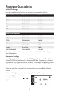
8. Trace the signal path with the receiver. (See Receiver Operations, page 8.)
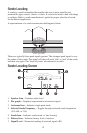
3M Dynatel Dyna-Coupler Clamp
If a direct connection to the target facility is not possible, use the Dyna-Coupler
clamp to apply the locating frequency on the metallic target conductor. In order
to trace a target using the Dyna-coupler method, both ends of the target must be
well grounded.
1. While the transmitter is off, attach the coupler cable to the Dyna-Coupler
clamp and plug it into the output jack of the transmitter.
2. Clamp the Dyna-coupler around the metallic target. The jaws of the coupler
must be fully closed.
3. Select 8 kHz or 82 kHz on the transmitter by pressing the frequency key.
4. Select High Output level for the best signal-to-noise ratio.
5. Trace the signal path with the receiver. (See Receiver Operations, page 8.)