


8472B Operating and Service Manual 7
Performance Tests
Performance Tests
Methods for testing detector specifications are given below. Refer to the
manuals of the equipment involved for specific operating instructions.
NOTE Multiple mismatch errors caused by attenuator SWR, power meter SWR,
and detector SWR should be taken into account, as well as the accuracy of
the indicator used to measure the detector’s output.
Frequency
Response Test
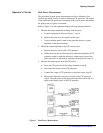
1. Using signal sources covering 10 MHz to 18 GHz with a 10 dB isolating
attenuator and a power meter, connect the power sensor to the attenuator.
Adjust the CW RF power level to
−
20 dBm input to the power sensor.
2. Without changing the RF power level of signal source, disconnect the
power sensor.
3. Connect the detector to the attenuator. Measure the dc voltage output
and record the measurement.
4. Change the frequency of the signal source and repeat steps 1 through 3.
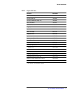
5. Since the detector follows a square-law response at this power level, its
output is proportional to power (P
dB
= 10 log V
o
). Total variation of
detector readings should meet specifications (refer to Table 1) for all
frequencies of interest across the band.
Higher Level
Sensitivity Test
1. Using signal sources covering 10 MHz to 18 GHz and a dc voltmeter or
oscilloscope as the indicator, connect the detector to the signal source.
Adjust the RF power level for a 100 mV detected output from the
detector, using a CW signal.
2. Disconnect the detector from the signal source and measure the RF
output level. The RF output level should be
≤ 0.35 mW.
3. Repeat steps 1 and 2 for all frequencies of interest across the band.
Low Level
Sensitivity Test
1. Using a signal source (covering 10 MHz to 18 GHz), a 10 dB attenuator,
and a power meter, connect the attenuator to the signal source and power
sensor to the attenuator. Adjust the RF power level for −20 dBm output
from the attenuator. Verify the ambient temperature.
2. Disconnect the power sensor from the attenuator and connect the
detector. Measure the dc voltage output from the detector. The output
should be > 5.0 mV at 25× °C. Between 20× °C and 30× °C the
sensitivity slope is typically −0.04 dB/× °C.
Match Test (SWR) 1. To verify the detector’s SWR specifications, use any system whose
measurement accuracies for SWR (residual SWR) are known.