


2-22 Chapter2
Quick Start: Learning How to Make Measurements
Learning to Make Reflection Measurements
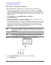
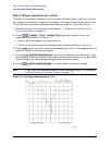
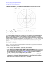
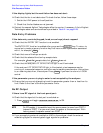
Figure 2-14 Example S
11
or Reflection Measurement Trace in Polar Format
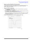
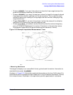
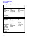
Measuring S
11
and S
22
or Reflection in a Smith Chart Format.
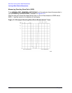
• Measuring Impedance
The amount of power reflected from a device is directly related to the impedance of the
device and the measuring system. Each value of the reflection coefficient (Γ) uniquely
defines a device impedance; Γ = 0 only occurs when the device and analyzer impedance are
exactly the same. The reflection coefficient for a short circuit is: Γ = 1 ∠ 180°. Every other
value for Γ also corresponds uniquely to a complex device impedance, according to the
equation:
Z
L
= [(1 + Γ) / (1 −Γ)] × Z
0
where Z
L
is your test device impedance and Z
0
is the measuring system's characteristic
impedance (usually 50Ω or 75Ω).
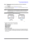
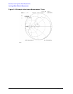
1. Press .
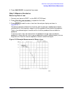
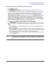
2. Press and turn the front
panel knob to read the resistive and reactive components of the complex impedance at
any point along the trace, as shown in Figure 2-15. Here the complex impedance is
6.4729 – j7.5569 Ω. This is the default Smith chart marker.
The marker annotation also gives the series inductance or capacitance (132.87 pF in
this example). The complex impedance is capacitive in the bottom half of the Smith
chart display and is inductive in the top half of the display.
Format
SMITH CHART
Scale Ref
AUTO SCALE
Marker Fctn
MARKER MODE MENU
SMITH MKR MENU