


Installation
3
AXB-MIDI MIDI Interface
Installation
Setting the DEVICE DIP Switch
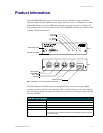
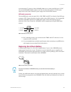
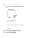
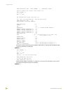
The 8-position DIP switch (see FIG. 1) sets the AXlink device number for the AXB-MIDI. The
device number must match the number assigned in the Axcess software program.
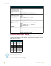
The Device DIP switch example shown in FIG. 2 is set to the factory default setting of 90
(2 + 8 + 16 + 64 = 90).
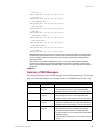
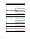
The AXlink device number range is 1-255, and is set according to the Device DIP switch positions
and their values shown in the following table:
Preparing Captive Wires for AXlink
Use a wire stripper and flat-blade screwdriver to prepare and connect the AXlink captive wires:
1. Strip 0.25 inch off the wire insulation for all four wires.
2. Insert the exposed section of each wire into the appropriate opening on the captive wire
connector according to the wiring diagrams shown in the Installation section of this manual.
3. Using a flat-blade screwdriver, turn the screws clockwise to secure the wire in the connector.
Wiring the AXB-MIDI
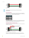
The AXB-MIDI requires 12.5 VDC to operate properly. The power can be supplied by the Central
Controller's power supply and AXlink cable or with an optional 12 VDC power supply. The
maximum wiring distance between the Central Controller and AXB-MIDI is determined by power
consumption, supplied voltage, and the wire gauge used for the cable.
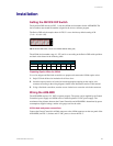
AXlink data and power connections
Connect the Central Controller's AXlink connector to the AXlink connector on the rear panel of the
AXB-MIDI (see FIG. 1) for data and 12 VDC power, as shown in FIG. 3.
FIG. 2 DEVICE DIP Switch, shown set to default address setting (90)
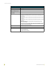
Device DIP Switch Settings
Position 12345678
Value 1 2 4 8 16 32 64 128
12345678