


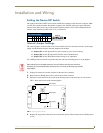


Installation and Wiring
8
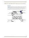
AXB-TC and AXB-TCR Television Controllers (& Receivers)
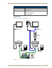
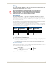
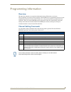
IR Emitter connections
Connect the CC-IRC IR Emitter to the IR Emitter connector, on the rear panel of the television controller
(FIG. 3) to transmit IR control signals to the television.
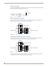
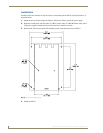
Axlink data and power connections
Connect the Central Controllers's AXlink connector to the AXlink connector on the rear panel of the
television controller for data and 12 VDC power, as shown in FIG. 4.
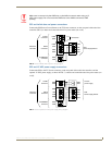
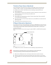
Axlink data and 12 VDC power supply connections
Connect the Central Controller’s AXlink connector to the AXlink connector on the rear panel of the
television controller, and the optional 12 VDC power supply, as shown in FIG. 5.
Use the 12 VDC power supply when the distance between the AMX system and television controller
exceeds the limits described in the Wiring Guidelines table on page 7.
FIG. 3 CC-IRC IR Emitter connector wiring diagram
FIG. 4 AXlink data and power wiring diagram
FIG. 5 AXlink Data and 12 VDC Power Supply Connections
IR EMITTER
connector
GND
SG
CC-IRC
Television
12 VDC
no connection
Axcess Control SystemAXlink connector
PWR
GND
PWR
AXP
AXM
GND
PWR
AXP
AXM
GND
PWR connector
12 VDC
12 VDC power supply
Axcess Control SystemAXlink connector
PWR
GND
PWR
AXP
AXM
GND
PWR
AXP
AXM
GND
PWR connector