


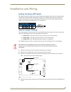
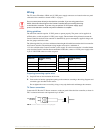


Installation and Wiring
9
A
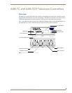
XB-TC and AXB-TCR Television Controllers (& Receivers)
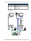
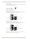
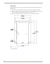
PCS and Axlink data and power connections
Connect the PCS Power Current Sensor to the TV Sensor connector, on the rear panel of the television
controller (FIG. 6) to detect and control the television power status (on or off).
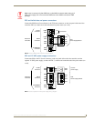
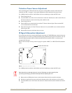
PCS and 12 VDC power supply connections
Connect the PCS to the TV Sensor connector, on the rear panel of the television controller, and the
optional 12 VDC power supply, as shown in FIG. 7, to detect and control the television power status (on
or off).
Make sure to connect only the GND wire on the AXlink connector when using a 12
VDC power supply. Do not connect the PWR wire to the AXlink connector's PWR
opening.
FIG. 6 PCS and AXlink data and power wiring diagram
FIG. 7 PCS and optional 12 VDC power supply wiring diagram
PWR
AXP
AXM
GND
PWR
AXP
AXM
GND
GND
PWR
SEN
GND
no connection
PCS
Power Supply Sensor
12 VDC
AXlink
TV SENSOR
Tel ev ision
Controller
connector
connector
connector
PWR
AXP
AXM
GND
PWR
AXP
AXM
GND
GND
PWR
SEN
GND
PCS
Power Supply Sensor
12 VDC
AXlink
TV SENSOR
Television
Controller
connector
connector
connector
GND
PWR
12 VDC
power supply