


Installation and Wiring
5
A
XB-TC and AXB-TCR Television Controllers (& Receivers)
Installation and Wiring
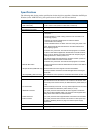
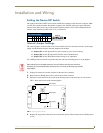
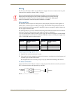
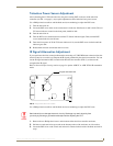
Setting the Device DIP Switch
The eight-position Device DIP switch sets the identification number for the television controller. Make
sure the device number matches the number assigned in the AXCESS software program. The quick
reference table below shows the switch positions and their numeric value. In the example below, the
numeric value of the Device DIP switch is 97 (1+32+64=97).
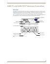
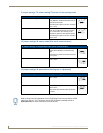
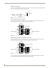
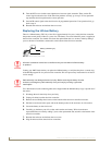
Internal Jumper Settings
The internal jumpers, located on the circuit card inside the television controller enclosure, set the input,
output, and IR attenuation modes. Internal jumper modes include:
Jumper JP1 sets the input mode for power sensing or power current sensing.
Jumper JP2 sets the IR output mode for IR or serial communication.
Jumper JP3 sets the IR attenuation mode for bypass or adjustment.
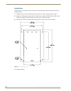
Use a Phillips-head screwdriver to open the enclosure and non-conducting pliers to set the jumpers.
1. Unplug all connectors from the rear panel of the television controller.
2. Remove the two Phillips-head screws on the bottom of the enclosure.
3. Pull the two enclosure halves apart and set the bottom portion of the enclosure on a flat surface.
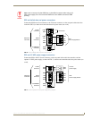
FIG. 1 shows the location of the internal jumpers.
4. Replace the top portion of the enclosure on the bottom portion. Then, refasten the two Phillips-head
screws.
DIP Switch Settings
Switch12345 6 7 8
Value 1248163264128
Static electricity can damage electronic circuitry. Before removing the enclosure,
discharge any accumulated static electricity from your body by touching a grounded
metal object.
FIG. 1 Internal jumper locations
JP1 jumper
JP3 jumper
JP2 jumper
front
12345678
ON
DEVICE