


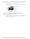
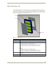


Mio Modero IR
18
Mio Modero Device Family
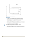
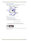
Mounting Procedure
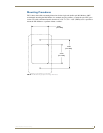
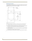
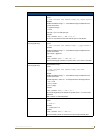
FIG. 15 shows the wallbox mounting dimensions for the Mio Modero IR. AMX recommends mounting
the Mio Modero IR in a standard one-gang wallbox, a conduit box per NEC specs section 370, with a
minimum internal clearance of 2-5/8" x 1-3/4" x 1-5/8" (HWD).
1. Use the cutout dimension for the wallbox to cutout the install surface for the Mio Modero IR.
2. Confirm that the terminal end of the AxLink cable is disconnected, and not receiving power.
3. If the faceplate is connected to the mounting frame, place a flathead screwdriver in the notch at the
bottom right of the Mio Modero IR, and pry the faceplate from the mounting frame.
4. Connect the AxLink power supply. The connector passes through the center of the mounting frame
and connects to the board.
5. Place the mounting frame on the wallbox; align the screw holes with the mounting holes and fasten
the mounting frame to the wallbox using the screws supplied.
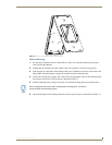
6. Attach the faceplate to the mounting frame first at the top and swing it to the bottom. See FIG. 16.
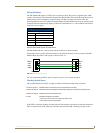
FIG. 15 Mio Modero IR mounting dimensions
2.250
[57.2 MM]
[83.4 MM]
3.282
[50.8 MM]
2.000