


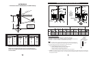
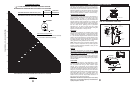
GROUND POLE INSTALLATION (1.2m System)
4
MIN.
DIA.
d
d
MIN.
DIA.
ANT
2.88" or
3.00" O.D.
2.88" or
3.00" O.D.
40"
C
L
72"
35.8"
35.8"
increased,
72"
40.9"
5
0" depth may be
w
ill increase
length of rebar
concrete and
a
ccordingly.
2"
2"
50"
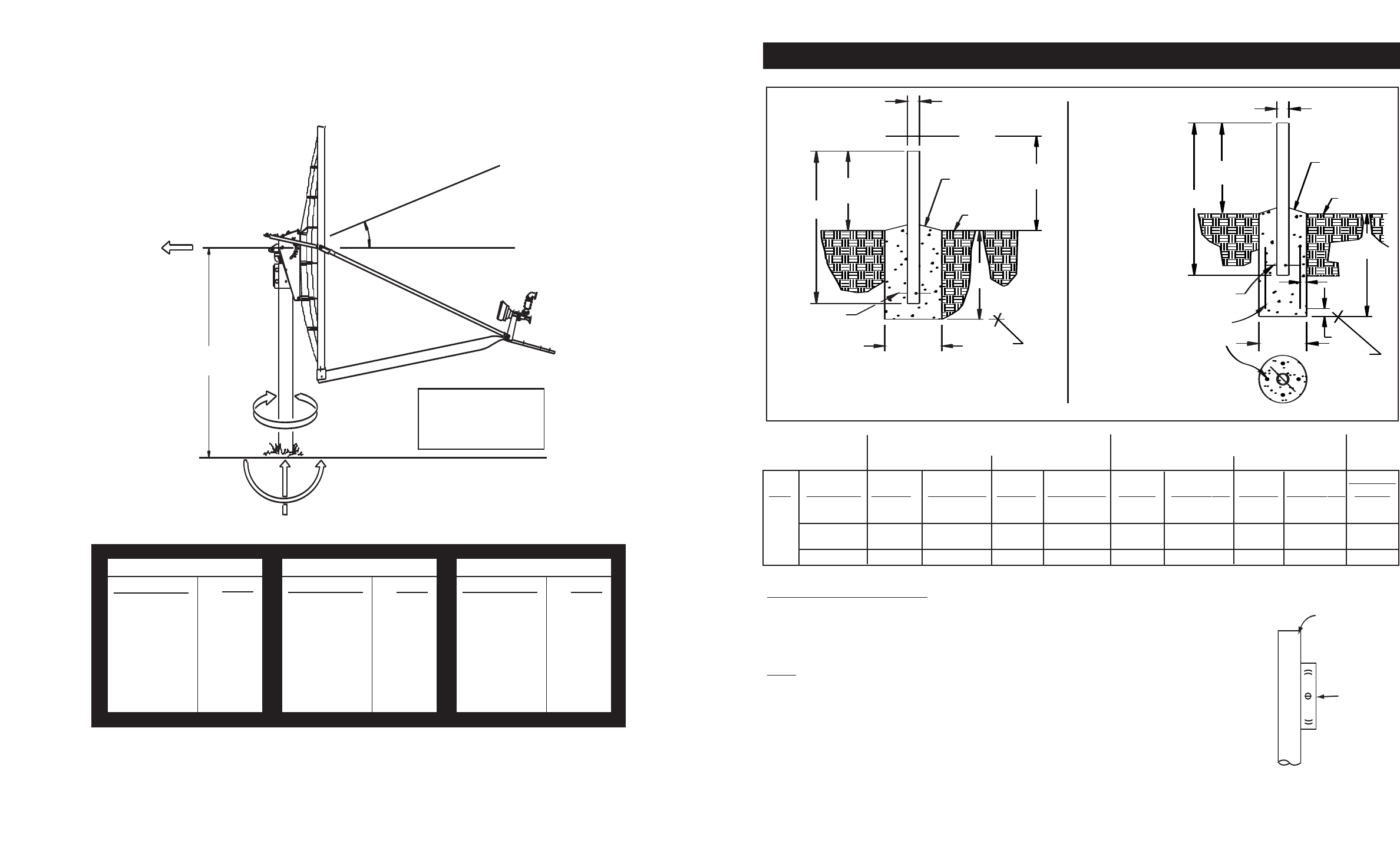
NOTE:
#3 REBAR x DIA. OF PIER, INSERT
FROST LINE
#3 REBAR x
DIA. OF PIER
INSERT THRU HOLE
IN TUBE & CENTER
AT 90
o
APART
(SEE NOTE)
(4)#3x24"MIN.
BELOW
T
HRU HOLE IN TUBE & CENTER
1" to 2"
WATER RUN OFF
GRADE
SLOPE FOR
BELOW
FROST LINE
APPROX.
1" to 2"
SLOPE FOR
(SEE
NOTE)
GRADE
WATER RUN OFF
GROUND
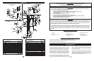
ANT WIND VEL. DIM “d” CONC VOL. DIM “d” CONC VOL. DIM “d’ CONC VOL. DIM “d” CONC VOL. POLE
80 MPH 8” 1.3 13” 3.4 8” 1.6 10” 2.5 “A” or
90 MPH 10” 2.0 16” 5.1 8” 1.6 12” 3.6 “B”
1.2M 100 MPH 12” 2.9 18” 6.5 8” 1.6 13” 4.2 “B” or
LFL 110 MPH 14” 3.9 21” 8.8 10” 2.5 16” 6.4 “C”
125 MPH
17”
5.8 24” 11.5 12” 3.6 19” 9.0 “D”
POLE SPECIFICATIONS:
Ground P
ole
“A”
= 2.88 O
.D. x .154 Wall (Sch 40) x 72” ASTM A53 or A501 Pipe
Ground P
ole
“B” = 3.00 O.D. x 9 Ga. (.148 Wall) x 72” Steel - CM PN 611685101
Ground Pole “C” = 2.88 O.D. x 2.88 O.D. x .276 Wall (Sch 80) x 72” Steel ASTM A53 or A501 Pipe
Ground Pole “D” = 3.00 O.D. x .250 Wall x 72” Steel ASTM 120 Mech Tubing
NOTE
:
Pole “B” is supplied from factory powder painted and with hole for #3 rebar and grounding screw.
Poles “A”, “C” and “D” are not supplied and must be field drilled
⁵⁄₈” dia. for #3 rebar and drilled .218
f
or
¹⁄₄-20 self tapping g
rounding scre
w and galvanized or painted for protection.
1 - P
ole and f
oundation design based on the f
ollowing criteria:
a)
Uniform building code exposure B or C and 1.5 stability factor.
b) Vertical soil pressure of 2000 pounds per square foot.
c) Lateral soil pressure of 400 pounds per square foot.
d)
Concrete compressiv
e strength of 2500 pounds per square inch in 28 da
ys
.
2 -
CAUTION - The foundation design shown does not represent an appropriate design for any specific locality since soil conditions vary
and may not meet design criteria given in Note 1.You should consult a local professional engineer to determine your soil conditions
and appropriate foundation.
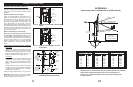
Exposure “B” Exposure “C” Exposure “B” Exposure “C”
PIER FOUNDATIONS DEEP FROST LINE FOUNDATIONS
Bubble
Level
Ground Pole
Must Be
Vertical In
All Directions
Within .19 Inches
At Top (0.3ß)
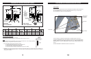
13
M
o
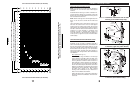
Based on 40.9" (1039 mm) from Mounting Surface of Center Line of Antenna
Values shown represent maximum forces for any wind direction and
include 1.5 F
s
. Height and exposure factors from uniform building code
are NOT included.
APPENDIX B
1.2m Antenna Survival Windloads at 125 MPH Velocity
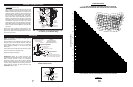
BEAM AXIS
MECHANICAL AXIS
(NORMAL TO ANTENNA FACE)
16.97
o
OFFSET
40.9" HEIGHT
(1039 mm)
F
H
M
T
F
V
F
H
= Horizontal Force
F
V
= Vertical Force
M
T
= Torsional Moment
M
O
= Overturning Moment
M
O
ELEVATION DEGREES
MECHANICAL BEAM
0 17
10 27
20 37
30 47
40 57
50 67
60 77
70 87
FORCE (POUNDS)
F
H
F
V
1285 -35
1217 -257
1182 -497
1071 -711
943 -857
822 -943
686 -985
515 -762
MOMENTS (FT-LBS/N-m)
M
T
M
O
500 4,380
488 4,148
464 4,029
421 3,650
357 3,214
299 2,802
232 2,338
178 2,096