


6
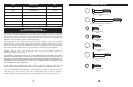
ASSEMBLY AND INSTALLATION
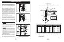
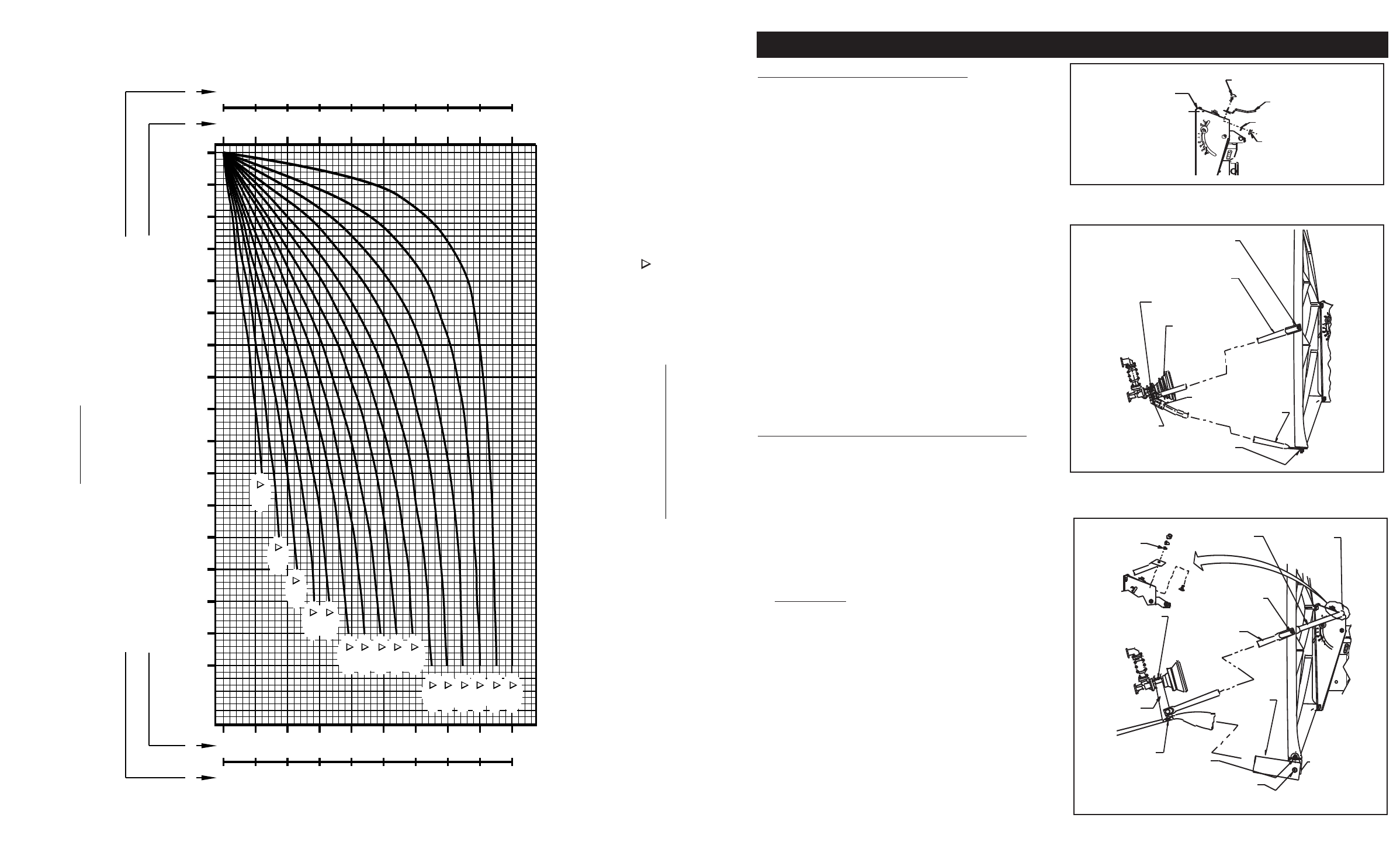
FEED AND FEED LEG INSTALLATION
NOTE: Long formed end of Side Feed Leg attaches to
the Reflector rim, short formed to side of Feed Support
Terminal.
Assemble Bottom Feed Leg to bottom of Reflector rim.
From the inside of Reflector rim, insert M6 x 16mm Hex
Bolt thru hole in rim and attach Bottom Feed Leg. Secure
with Lock Washer and Hex Nut.
NOTE: Bottom Feed Leg is the one with slight bend, with
lance, on one end, and is shorter than the Side Feed
Legs.
Leave all hardware loose. Insert Bottom Feed Leg end
with lance into socket hole in center of Feed Support
Terminal. Twist to engage lances. Attach left and right
Feed Support Legs to Feed Support Terminal, securing
with M6 x 16mm Hex Bolts and Lock Washers. Refer to
Instruction for Feed Assembly to assemble Feed
Assembly and ODU to Terminal Block. Tighten and
torque all hardware to Terminal Block and Reflector to
4 ft-lbs (5.4 N-m). Tighten two screws in Terminal Block
socket equally.
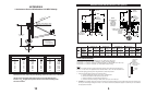
FEED AND FEED SUPPORT TUBE INST
ALLATION
MEDIUM DUTY
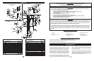
Assemble “U” Clip to bottom of Reflector using M6 x
22mm Round Head Square Neck Bolt, Lock Washer and
Hex Nut. Insert bottom Feed Support Tube into “U” Clip
and secure with M6 x 55mm Round Head Square Neck
Bolt and elastic Lock Nut. (Ref. Fig. 1.5 & 1.6) Assemble
Feed Support Block (supplied with Feed package) to
Feed Support Tube, using two M6 x 16mm Hex Bolts and
Lock Washers.
96cm System (Ref. Fig. 1.5)
Attach Side Feed Legs and Braces to left and right
sides of Reflector using M6 x 20mm Hex Bolts, Lock
Washers and Hex Nuts. (NOTE: Long formed end of
F
eed Leg attaches to Reflector
.
Short formed end of
Brace attaches to inside of Reflector rim.) Attach flat-
ten end of Brace to top of Mount Housing using M6 x
22mm Round Head Square Neck Bolts, Tooth Lock
Washers, Flat Washers and Hex Nuts. Round Head
Square Bolt fits on the underside of Mount Housing
top, flatten end of Brace on top side of Mount
Housing, Tooth Lock Washer on top of flatten end of
Brace, then Flat Washer and Hex Nut.
Attach Side Feed Legs to support Block using M6 x
20mm He
x Nuts and Lock Washers. Leave all hard-
ware loose.
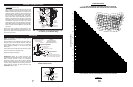
MOUNT
ASSEMBLY
ROUND HEAD SQUARE
NECK BOLT (2 REQ)
E
XTENSION
PLATE
LOCK WASHER
(
2 REQ)
H
EX NUT
(2 REQ)
FIG. 1.3 - Installation of Extension Plate to AZ/EL
Housing (1.2m medium Duty Only)
TOOTH
WASHER
BRACE (1 L.H.
& 1 R.H.)
RD HD SQ NK BOLT
TOOTH WASHER
FLAT WASHER
HEX NUT
(2 REQ)
SIDE FEED LEG
(2 REQ)
HEX BOLT
FLAT WASHER
(2 REQ)
M6 x 20mm
HEX BOLTS
LOCK WASHERS
HEX NUTS
(2 REQ-BOTH SIDES)
MOUNTING
BLOCK
"U" CLIP
BOTTOM FEED
SUPPORT TUBE
HEX BOLT
LOCK WASHER
(2 REQ)
RD HD SQ
NK BOLT
FLAT WASHER
LOCK WASHER
HEX NUT
RD HD SQ
NK BOLT &
ELASTIC LOCK
NUT
FIG. 1.5 - Installation of Feed/Feed Support Legs
to Antenna (96cm Medium Duty)
HEX BOLT
FLAT WASHER
H
EX NUT
(2 REQ BOTH SIDES)
SIDE FEED LEG
(2 REQ)
HEX BOLT
FLAT WASHER
(
2 REQ BOTH SIDES)
FEED HORN/FEED ASSY
w
/FEED SUPPORT
BLOCK
HEX BOLT
L
OCK WASHER
(2 REQ)
HEX BOLT
LOCK WASHER
HEX NUT
FEED SUPPORT
TERMINAL
BOTTOM FEED
LEG
FIG. 1.4 - Installation of Feed/Feed Support Legs
to Antenna (Light Duty, 96cm Shown)
0 5 10 15 20 25 30 35 40 45 50 55 60 65 70 75 80
180
190
200
210
220
230
240
250
260
270
180
170
160
150
140
130
120
110
90
270
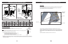
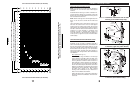
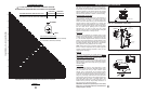
[AZIMUTH COLUMN READING WHEN EARTH STATION IS WEST OF SATELLITE]
[AZIMUTH COLUMN READING WHEN EARTH STATION IS EAST OF SATELLITE]
EARTH STATION ANTENNA LATITUDE (IN DEGREES NORTH OR SOUTH OF EQUATOR)
EARTH STATION ANTENNA AZIMUTH (IN DEGREES)
EARTH STATION ANTENNA AZIMUTH (IN DEGREES)
" L" IS THE DIFFERENCE BETWEEN THE EARTH STATION
ANTENNA SITE LONGITUDE AND THE SATELLITE LONGITUDE
AZIMUTH CHART
CHART 3
0
O
5
O
10
O
15
O
20
O
25
O
30
O
35
O
40
O
45
O
50
O
55
O
60
O
65
O
70
O
75
O
NORTHERN
HEMISPHERE
SOUTHERN
HEMISPHERE
WEST EASTWESTEAST
0
10
20
30
40
50
60
70
80
90
360
350
340
330
320
310
300
290
280
270
11