


NOTE: All installations to conform to latest issue of
National Electrical Code.
Ground antenna mount assembly and feed cables in
accordance with current National Electrical Code and
local electrical codes. Figure 2.0 and 2.1 illustrates
typical grounding methods for the ground pole and
feed cables.
Clamps that provide a solid connection between ground
wire and ground source should be used.
Tighten and torque all hardware.
IMPOR
T
ANT
:
Sealing RF Coaxial Connector
:
The
copper-plated center conductor in the RF coaxial cable,
which connects receiv
er to LNB, can experience
electrolysis corrosion at the LNB connector
.
Moisture
and DC current causes this type of corrosion. To prevent
corrosion, apply a moderate coat of silicon grease to the
center conductor and wr
ap the entire connection with
CO
AX-SEAL
®
tape to seal.
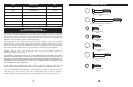
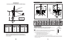
ASSEMBLY AND INSTALLATION
1.2m System (Ref. Fig. 1.6)
Attach Side Feed Legs and Braces to left and right
sides of Reflector using M6 x 20mm Hex Bolts, Lock
W
ashers and Hex Nuts. (NOTE: Long formed end of
Feed Leg attaches to Reflector. Short formed end of
Brace attaches to inside of Reflector rim.) Attach flat-
ten end of Brace to Extension Plate, using M6 x
22mm Round Head, Square Neck Bolts, Tooth Lock
Washers, Flat Washers and Hex Nuts. Round Head
Square Bolt Fits on the top of Extension Plate. Tooth
Lock Washer fits between the flatten end of Brace
and Extension Plate, then Flat Washer and Hex Nut.
Attach Side Feed Legs to Support Block using M6 x
20mm Hex Nuts and Lock Washers. Leave all hard-
ware loose.
Tighten and torque hardware securing Braces, Side
Legs, and “U” Clip to Reflector and Support Block to 4 ft-
lbs (5.4 N-m). Tighten and torque M6 x 55mm “U” Bolt to
18-22 in-lbs (2-2.5 N-m).
TOOTH WASHER
BLOCK
"U" CLIP
BRACE
SIDE FEED
LEGS
(2 REQ)
RD HD SQ
NK BOLT &
ELASTIC LOCK
NUT
BOTTOM FEED
SUPPORT TUBE
HEX BOLT
LOCK WAHER
(2 REQ)
RD HD SQ
NK BOLT
FLAT WASHER
LOCK WASHER
HEX NUT
RD HD SQ NK BOLT
TOOTH WASHER
FLAT WASHER
HEX NUT
(2 REQ)
M6 x 20mm
HEX BOLTS
LOCK WASHERS
HEX NUTS
(2 REQ-BOTH SIDES)
HEX BOLT
FLAT WASHER
(2 REQ)
FIG. 1.6 - Installation of Feed/Feed Support Legs
to Antenna (1.2m Medium Duty)
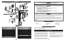
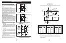
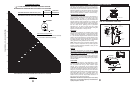
NOTE: ALL INSTALLATION TO CONFORM
TO THE LATEST ISSUE OF THE
NATIONAL ELECTRIC CODE.
IMPORTANT
DRILL HOLE AND ATTACH
GROUND BEFORE POURING
CONCRETE INSIDE GROUND POLE.
GROUND POLE
GROUND LUG
25"-29"
APPROX.
GROUND WIRE
(TYPICAL #10 AWG COPPER, #8 ALUMINUM)
REFER TO NEC SECTION 810 AND LOCAL ELECTRIC
CODES FOR THE SPECIFIC AREA REQUIREMENTS.
APPLY SEALANT HERE, AFTER ASSEMBLY,
TO IMPROVE CORROSION RESISTANCE
DRILL HOLE THRU ONE WALL WITH
7/32" DIA. TWIST DRILL
1/4" EXTENSION TOOTH LOCK WASHER
1/4"-20 UNC x 5/8" HEX HEAD,
TYPE "D" POINT, SELF TAPPING SCREW
FIG. 2.0 - Typical Electrical Grounding for
Antenna Ground Pole
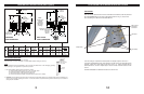
GROUNDING
*GROUND BLOCK
NEC SECTION 810-20
*GROUNDWIRE
NEC SECTION 810-20
*ITEMS NOT
INCLUDED
*COAXIAL CABLE
TO RECEIVER
*COAXIAL CABLE
FROM LNB
FIG. 2.1 - Grounding Feed Cables
7
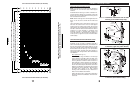
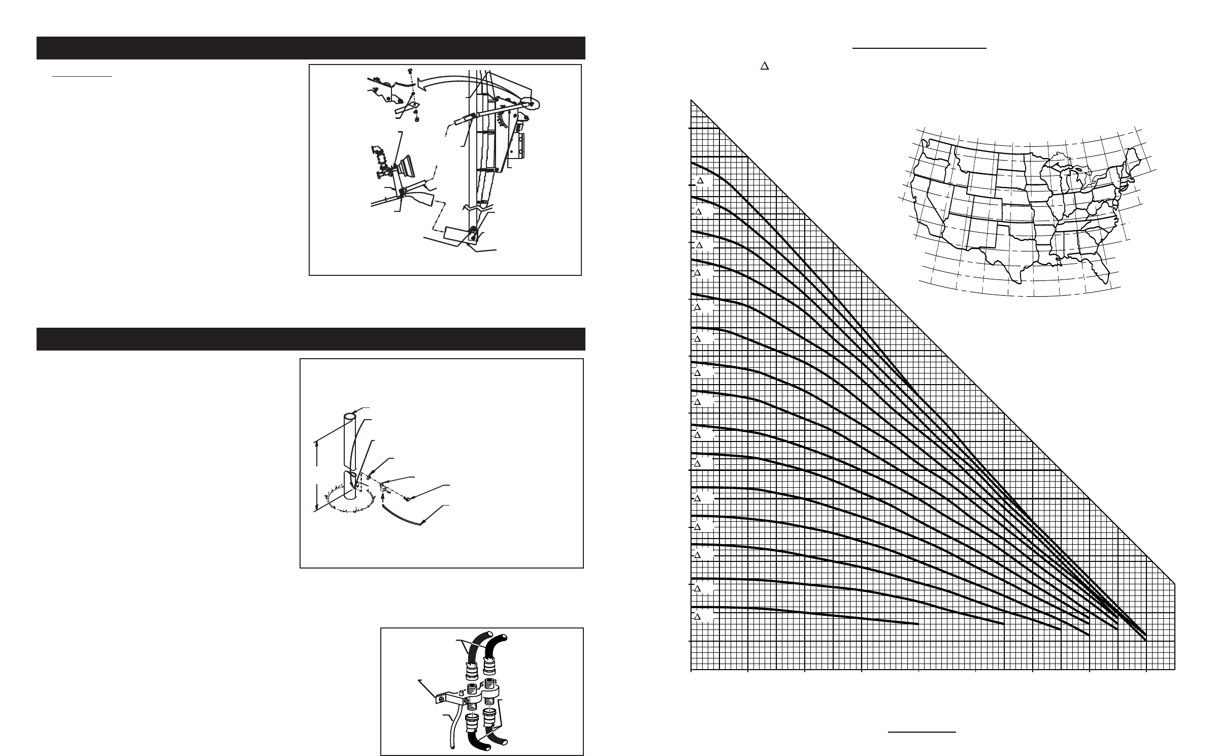
90
80
70
60
50
40
30
20
10
0 10 20 30 40 50 60 70 80
0
EARTH STATION LATITUDE IN DEGREES NORTH OR SOUTH OF EQUATOR
ELEVATION IN DEGREES
" L" IS THE DIFFERENCE BETWEEN THE EARTH STATION
ANTENNA SITE LONGITUDE AND THE SATELLITE LONGITUDE
ELEVATION CHART
CHART 2
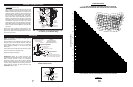
5
O
10
O
15
O
20
O
25
O
30
O
35
O
40
O
45
O
50
O
55
O
60
O
65
O
70
O
75
O
50
O
125
O
120
O
115
O
110
O
105
O
100
O
95
O
90
O
85
O
80
O
75
O
70
O
65
O
50
O
47.5
O
45
O
42.5
O
40
O
37.5
O
35
O
32.5
O
30
O
27.5
O
25
O
47.5
O
45
O
42.5
O
40
O
37.5
O
35
O
32.5
O
30
O
27.5
O
25
O
10