


5
E
N
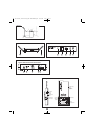
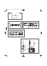
Antenna Position (Fig. B1)
1. ANTENNAS: Position the antennas as shown in Figure B1.
2. AF PEAK INDICATOR: Indicates when maximum transmitter
modulation without distortion has been reached. Not affected by
position of Volume control (Fig. C).
3. LED WINDOW: LED Display indicates channel setting and scanning
operation.
4. DIVERSITY INDICATORS: Indicates which antenna (A or B) has
better reception and is in operation.
5. SELECT BUTTON (for manual channel selection): Press the
Select button repeatedly until desired channel is reached. Press and
hold the Set/Scan button to manually set the receiver to indicated
channel. Channel number will stop flashing. (A brief touch of the
Set/Scan button will revert to previously set channel). If the Set
button is not pressed within 10 seconds to confirm the selection,
the system will revert to its original channel.
Front Panel Controls and Functions (Fig. B2)
6. SET/SCAN BUTTON: The Set/Scan button can be used in two
ways: 1) in conjunction with the Select button to permit manual
selection of an operating channel in Manual Set Mode (see
“Select button” description above); and 2)Automatic Scan/Set
Mode, to initiate the automatic channel scan and selection, as
follows:
Automatic Scan/Set Mode: Press and hold the Set/Scan button
for about two seconds. The current channel will flash three times
quickly; then the system will begin to scan for the next open
channel. When it finds an open channel, it will flash the open
channel three times and then set the channel. (If an open channel is
not found, the automatic scan will return to the original channel and
flash 5 times.)
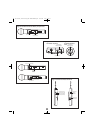
Rear Panel Controls and Functions (Fig. C)
8. UNBALANCED AUDIO OUTPUT JACK:
1
/
4
” phone jack. Can be
connected to an unbalanced aux-level input of a mixer, guitar amp
or tape recorder.
9. AF LEVEL (VOLUME) CONTROL: Adjusts audio output level of both
AF Output jacks; maximum output is fully clockwise.
10. BALANCED AUDIO OUTPUT JACK: XLRM-type connector. A
standard 2-conductor shielded cable can be used to connect the
receiver output to a balanced microphone-level input on a mixer or
integrated amplifier.
11. CORD HOOK: Loop the cord around the cord hook to keep the DC
plug from pulling out accidentally.
12. POWER INPUT JACK: Connect the DC plug from the included in-
line AC adapter.
Battery Selection
Two 1.5V AA alkaline batteries are recommended.
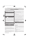
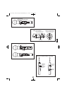
UniPak™ Transmitter Battery Installation
1. Open the transmitter door by first pulling the catch down and then
sliding the door upward (Fig. D).
2. Observe correct polarity as marked and carefully insert two fresh
1.5V AA alkaline batteries (Fig. D).
3. Slide the door closed, making certain it clicks securely in place.
Handheld Transmitter Battery Installation
4. Unscrew the lower body cover, slide it downward, and remove it to
expose the battery compartment.
5. Observe correct polarity as marked inside the battery compartment
and carefully insert two fresh 1.5V AA alkaline batteries. Insert the
first battery and slide it toward the spring contact. Then insert the
second battery into the space remaining. Make certain the batteries
are fully seated in the battery compartment. (Fig. E)
6. Slide the lower body cover back on and screw the housing together.
Do not overtighten.
Note: Remove batteries from the handheld transmitter starting at
the bottom end, where finger indents in the battery housing are
provided for easy grip.
Power/Mute/Battery Indicator
After the battery is installed, press and hold the power button until the
battery indicator LED turns green (Fig. F & G). (It will turn red first;
keep holding until it turns green). If the battery indicator LED does not
light up when the power button is pressed, the batteries are installed
incorrectly or they are dead. The LED will flash to indicate low-battery
condition.
Handheld Transmitter Bottom View (Fig. G)
Mute Function
With the transmitter on, a slight touch of the Power/Mute button will
toggle between muted and unmuted operation. Red LED indicates
muted operation. Green LED indicates unmuted operation.
UniPak Transmitter Input Connection
Connect an audio input device (microphone or guitar cable) to the
audio input connector on the top of the transmitter. A number of
Audio-Technica professional microphones and cables are available
separately, pre-terminated with a UniPak input connector (see
“Optional System Accessories” on page 7).
UniPak Transmitter Antenna
The UniPak transmitter includes a permanently-attached flexible
antenna. For best results, allow the antenna to hang freely and full
length from the transmitter. If the received signal is marginal,
experiment with different transmitter positions on your body or
instrument; or try repositioning the receiver. Do not attempt to
remove, replace or change the length of the transmitting antenna.
UniPak Transmitter Top View (Fig. F)
Receiver Controls and Functions
Transmitter Setup, Controls and Functions
Plug in the receiver.
Receiver On…
The LED display will light up. If either A or B diversity indicators lights
up at this point (without transmitter on) there may be interference in
the area. If this occurs, change the operating channel.
How to Make Operating Channel Changes
Operating channel changes (frequency changes) may be made in two
ways: manually and automatically.
To change channel manually
Press the Select button repeatedly until desired channel is reached.
Press and hold the Set/Scan button to manually set the receiver to
indicated channel. Channel number will stop flashing. (A brief touch of
the Set/Scan button will revert to previously set channel). If the Set
button is not pressed within 10 seconds to confirm the selection, the
system will revert to its original channel.
System Operation
See illustration figures page 2 See illustration figures page 3
OM 700 Series (March 2009).qxd:12MAY3000OM.qxd 12/03/09 9:58 Page 5