


128-7767
10 of 19
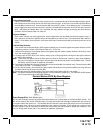
A. Shock Sensor By Pass:
If there is Shock Sensor used with an alarm system and it is not shunted during the Remote Start activation period,
then vibration from the running vehicle can cause the alarm to trigger. In this case, connect the Light Blue Wire to
terminal #86 of a external relay. Connect terminal #85 of the relay to a fused + 12 volt battery source. Cut the shock
sensor trigger wire and connect one end of the cut wire to terminal #30 and the other end of the cut wire to terminal
#87a. Just before the Remote Start unit is activated, the relay contacts will open, preventing the shock sensor's
operation until the Remote Start unit shuts off.
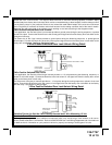
B. Ignition 3 Output:
Some newer vehicles use a third ignition wire, which is required to start and keep the vehicle's engine running. If
this is the case, connect the Light Blue wire to terminal #86 of an external relay. Connect terminal #30 & #85 to a
fused + 12 volt battery source rated for a minimum of 25 Amp. Connect terminal #87 to the third ignition wire in the
vehicle.
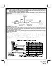
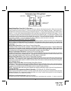
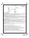
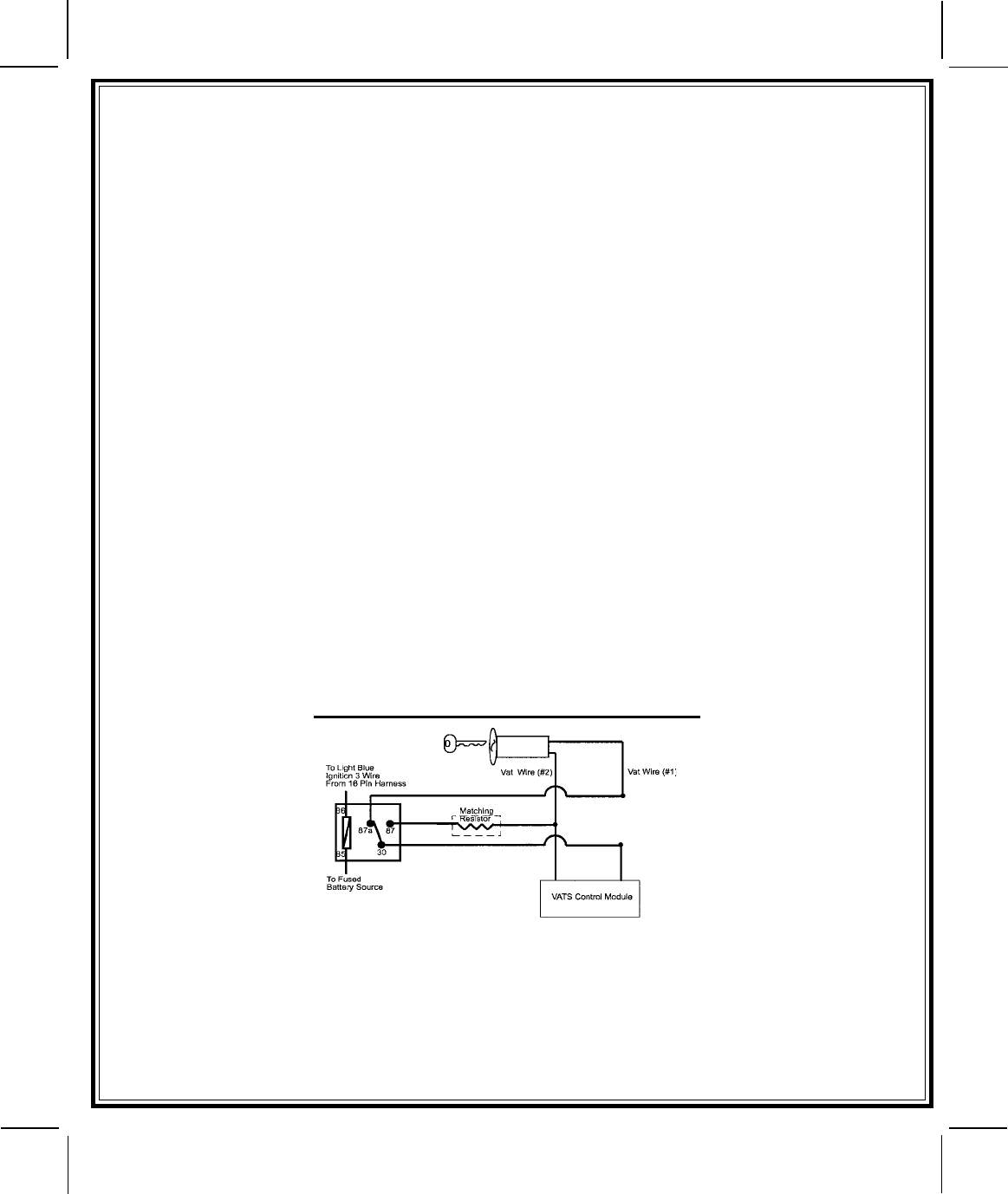
C. GM VATS Key Override:
If the vehicle has the General Motors VATS system installed, you will need to bypass the system while the vehicle
is operating under the control of the Remote Start Unit. To Do This;
1. Measure the resistance of the resistor pellet on the ignition key then select a resistor within 5% of the key's value
from the resistor pack supplied.
2. Locate the pair of VATS wires in the vehicle, usually a pair of thin gauge wires running from the ignition switch to
the VATS control module.
NOTE: These wires are typically White w/ Black trace and Violet w/ Yellow trace, however in later model Cadillacs,
they are run through an orange sleeve, and are either both Black, both Yellow, or both White wires. Consult
the factory service manual for additional information.
3. Connect the Light Blue Wire from the Remote Start Unit to terminal #86 of an external relay. Connect terminal #85
of the relay to a fused + 12 volt battery source.
4. Cut (#1) wire (as shown), and connect the ignition switch side of the cut wire to terminal #87a of the relay. Connect
the other side of the (#1) wire to terminal #30.
5. Connect the previously selected resistor from terminal #87 to the second (#2) wire (as shown).
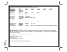
NOTE: The above information and following diagram is for the GM VATS system only. For GM PASS LOCK System
you will require the Audiovox AS-PASS II Module.
General Motors VATS By-Pass Diagram
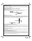
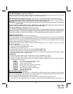
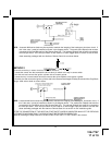
Green/Orange Wire: Tach Sensor Input
This wire will continually monitor the engine tach rate while the unit is under power of the Remote Start module. This
wire will be routed to the vehicle ECM tach input or through the firewall into the engine compartment and connect to
the negative side of the ignition coil. This Remote Start unit learns the tach rate of the vehicle and in most cases will
operate properly from one multi coil pack regardless of the number of cylinders. If the vehicle has a single coil unit
for each cylinder, it may be necessary to connect this wire to more than one cylinder for proper tach reference. See
multi coil wiring detail shown later in this manual for additional information.
10